
wCore PCB and USB PCB
Manufacturer: antilog devices
Product ID: P-COR-01
This is the main MIDIbox Core PCB: a carrier board for the Waveshare Core407v MCU.
Weight: 40 grams
in stock
22.98 €
incl. VAT, excl. shipping
Bill of Materials / Placement Guide
Label
Package
Name
Side
Part Link
Notes
Required Mouser parts
Can be directly transferred into your
mouser cart by copying & pasting the text below into the mouser part list import tool (you
may need to log in at mouser before the tool is available):
https://www.mouser.com/tools/part-list-import.aspx
https://www.mouser.com/tools/part-list-import.aspx
80-C1206C104M5R|3
512-1N4148TR|2
534-7695|2
771-74HCT125D-Q100J|2
595-SN74HC595DR|1
571-1-215570-0|2
538-22-23-2031|1
517-30310-6002|4
649-93992-436HLF|1
517-N2516-6002RB|3
650-NANOSMDC075F-2|1
652-CR1206JW-220ELF|2
652-CR1206JW-331ELF|1
660-MF1/4DCT52R1002F|2
652-CR1206JW-103ELF|1
660-MF1/4DCT52R2201F|2
652-CR1206JW-222ELF|2
660-MF1/4DCT52R1001F|1
652-CR1206-JW-102ELF|3
71-CRCW1206560RJNEB|1
660-MF1/4DCT52R2203F|1
660-MF1/4LCT52R331J|1
490-SJ1-3535NG|1
611-1101M2S4AV2BE2|1
512-BC33725TAR|1
771-PRTR5V0U2X-T/R|1
538-67068-8000|1
538-89485-8000|1
Optional (DNF) Mouser parts
These parts are not required for a normal build - in general: don't buy them! They would go to the greyed-out locations specified as DNF ("do not fit") in the BOM above. If you want them anyways, e.g. for a special usecase, you can also copy & paste them into your mouser cart:
534-7695|2
517-30310-6002|5
652-3306F-1-103|2
660-MF1/4DCT52R1002F|1
660-MF1/4DCT52R1001F|1
512-BC33725TAR|1
Required midiphy parts
You can manually add these to your cart
using the links below. If you are buying a midiphy essential kit, these should be included
already. If you are buying plain PCBs, these are necessary to complete your build.
The BOM checker 'bot says:
All parts referenced from the CAD master files have been validated. The BOM should be safe to order!*
* Disclaimer: although we have taken the best care possible, we cannot guarantee 100%
accuracy and we cannot be held liable for erroneous orders when using
this tool, including (but not limited to) incorrect quantities and/or
types of components ordered through midiphy or other suppliers.
Video Build Tutorial
Assembly
The following build order is suggested:
R33A-D (3x 1k and 1x 560R) located near J15_S on the top side
R7B and R8B (2k2 1206) on the bottom side
C1A, C1B and C2 (100n 1206) on the bottom side
IC1A, IC1B (74HCT125) and IC2 (74HC595) on the bottom side
Top-side THT resistors R7A 2k2, R8A 2k2, R11 1k, R12 10k, R13 1k and diode
Bottom-side THT resistors R101 220k, R102 330R
Top-side transistor and trimpots
Bottom-side JPA0 header
Bottom-side 2*25 pin female headers
for a SEQ v4+ build, consider omitting headers J4B, J5A, J5B, J10A, J10B and J18
Top-side male headers, except for J1
Solder J1 in conjunction with the USB module
Mounting brackets if needed
Schematic and Notes
. The following parts are different:
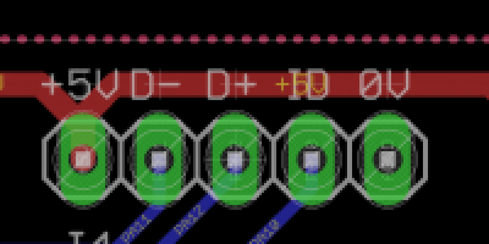
USB entry (J1)
This header supplies +5V, 0V, USB data and the ID state. Normally it will be connected to the USB module by a short cable.
This header supplies +5V, 0V, USB data and the ID state. Normally it will be connected to the USB module by a short cable.
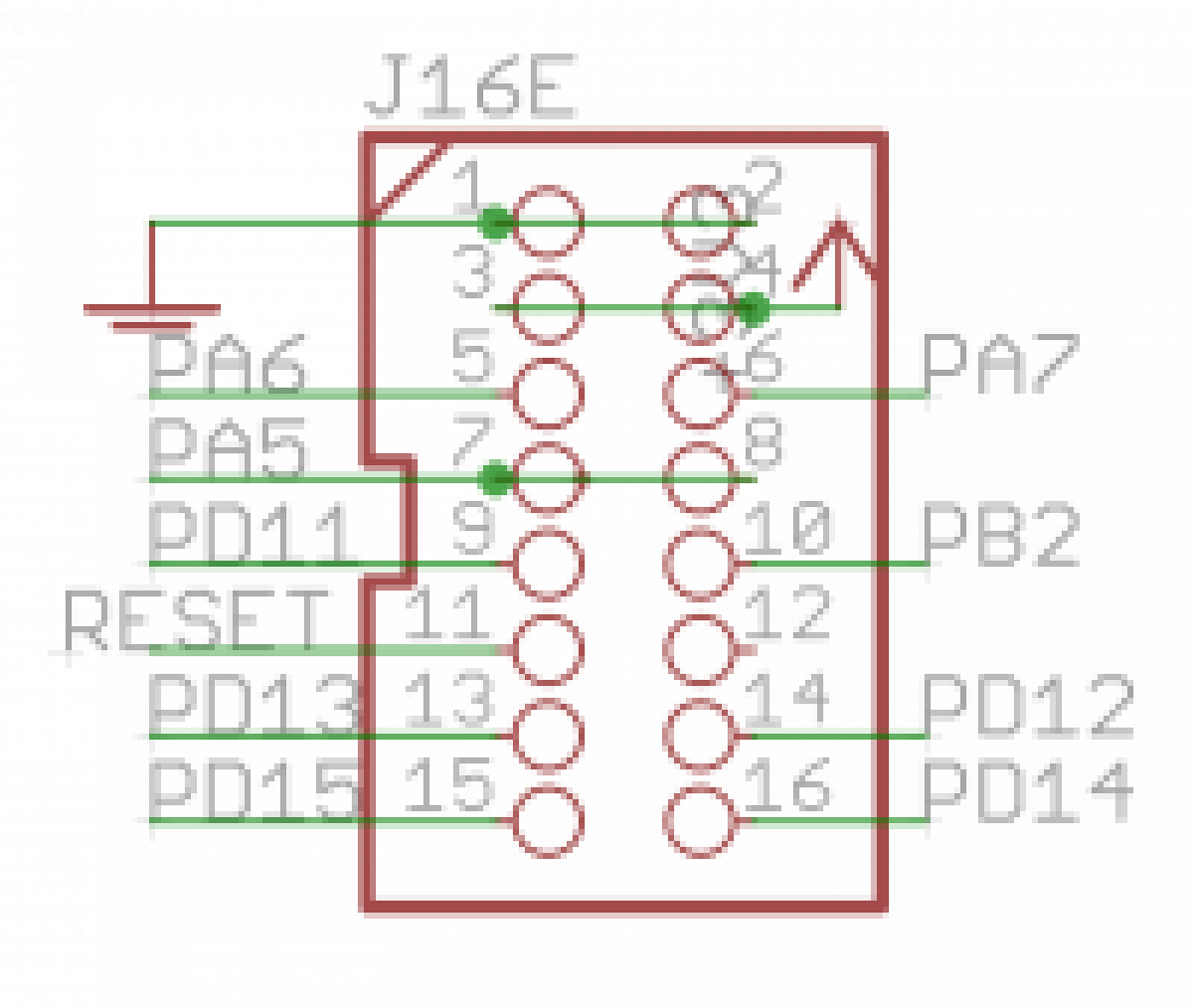
Extended port (J16E)
The original J16 functionality is preserved, but extra pins are available on an IDC16 header. These include the Reset signal and pins normally controlling LEDs. This header is normally connected to the RES-SD module.
The original J16 functionality is preserved, but extra pins are available on an IDC16 header. These include the Reset signal and pins normally controlling LEDs. This header is normally connected to the RES-SD module.
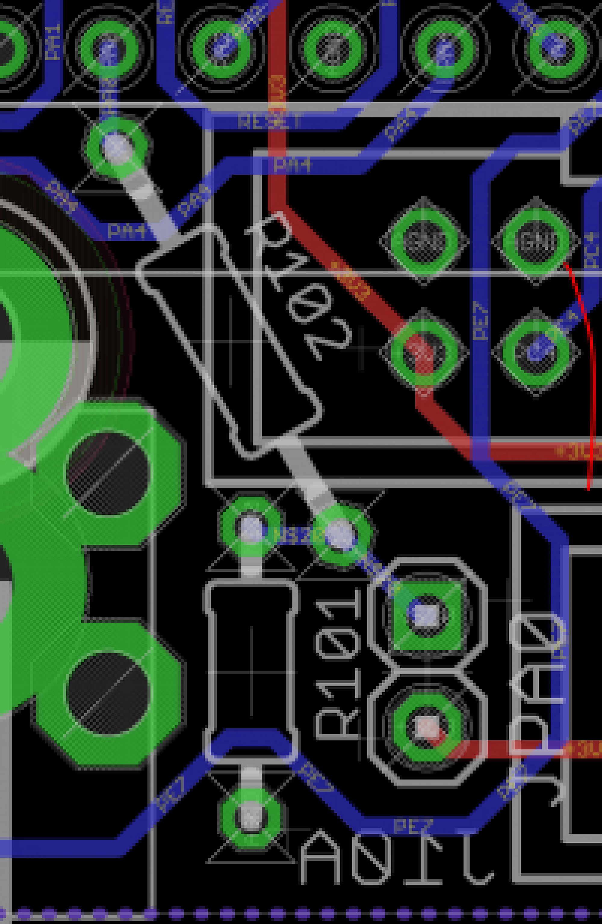
User button (JPA0)
This jumper replaces the “bootloader” functionality of the Discovery board's blue button. It could be wired to an external panel control if needed.
This jumper replaces the “bootloader” functionality of the Discovery board's blue button. It could be wired to an external panel control if needed.