


product details
midiphy Wirescanner PCB
Product ID: P-UTL-02
Old version of DIY midiphy cable tester. Validate IDC and micromatch 8/10/16 pin cables - with graphical 16x16 LED Matrix connectivity visualization. New version with case: see K-UTL-02.
Weight: 50 grams
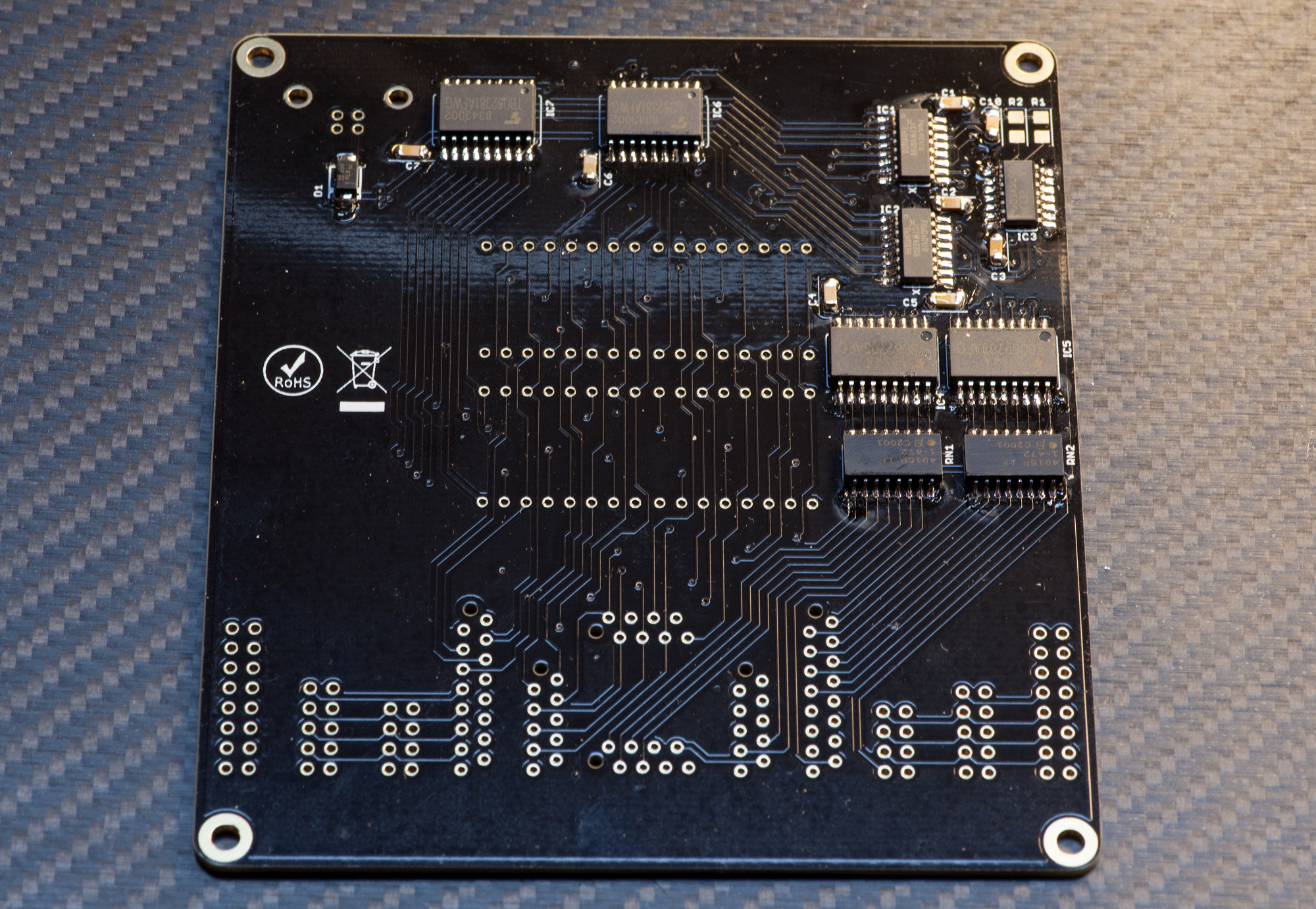
Bill of Materials / Placement Guide
Label
Package
Name
Side
Part Link
Notes
Required Mouser parts
Can be directly transferred into your
mouser cart by copying & pasting the text below into the mouser part list import tool (you
may need to log in at mouser before the tool is available):
https://www.mouser.com/tools/part-list-import.aspx
https://www.mouser.com/tools/part-list-import.aspx
80-C1206C104M5R|7
77-VJ1206Y223JXAAC|1
621-SBR1U150SA-13|1
771-74HC4017D-T|2
595-SN74HC132DR|1
757-TBD62783AFGEL|2
757-TBD62381AFWGEHZ|2
517-N2516-6002RB|2
710-61201021621|2
517-30308-6002HB|2
571-1-215079-6|2
571-12150790|2
571-7-215079-8|2
652-CR1206-JW-473ELF|1
652-CR1206-JW-472ELF|1
652-4816P-1LF-4.7K|2
538-67068-7041|1
Required midiphy parts
You can manually add these to your cart
using the links below. If you are buying a midiphy essential kit, these should be included
already. If you are buying plain PCBs, these are necessary to complete your build.
The BOM checker 'bot says:
All parts referenced from the CAD master files have been validated. The BOM should be safe to order!*
* Disclaimer: although we have taken the best care possible, we cannot guarantee 100%
accuracy and we cannot be held liable for erroneous orders when using
this tool, including (but not limited to) incorrect quantities and/or
types of components ordered through midiphy or other suppliers.
Recommended products
These additional products may be of interest:
Introduction Video
Photo Tutorial
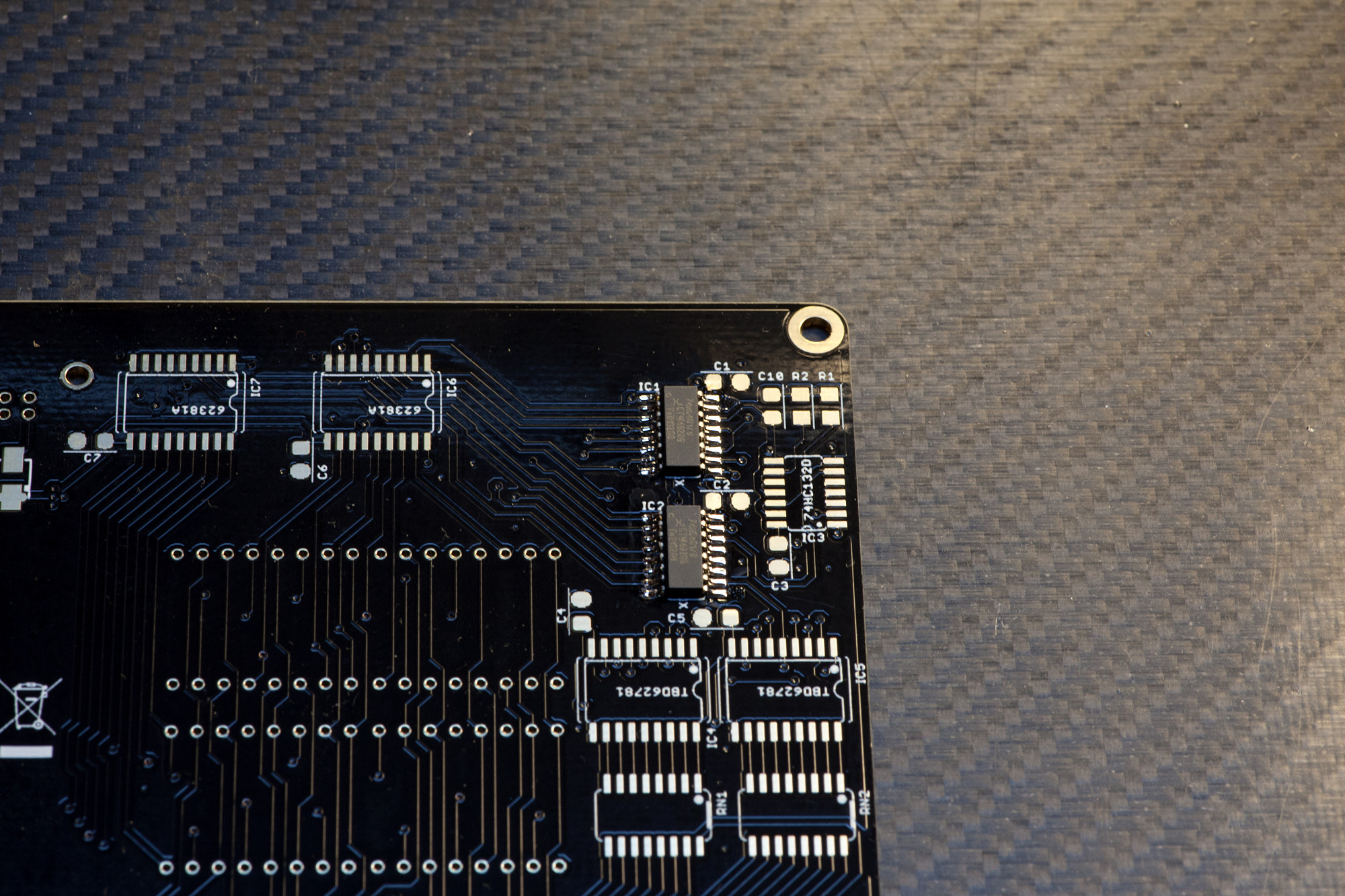
Step 1: 74HC4017
Solder IC1 and IC2 observing polarity.
Make sure you align the marking on the pin with the notch on the silkscreen. An easy method to solder the IC is to solder two legs on one side first, then apply your flux pen and solder first on the other side and then on the side you "tacked". Here's an in-depth description of the technique:
After soldering, check all pins with a loupe/magnifying glass for unwanted bridges and for proper contact to the PCB, also check from the sides, as there might be unwanted "lift" and a pin might not have reached a pad on the PCB. The above tutorial video link explains how to fix errors with desoldering braid, too.
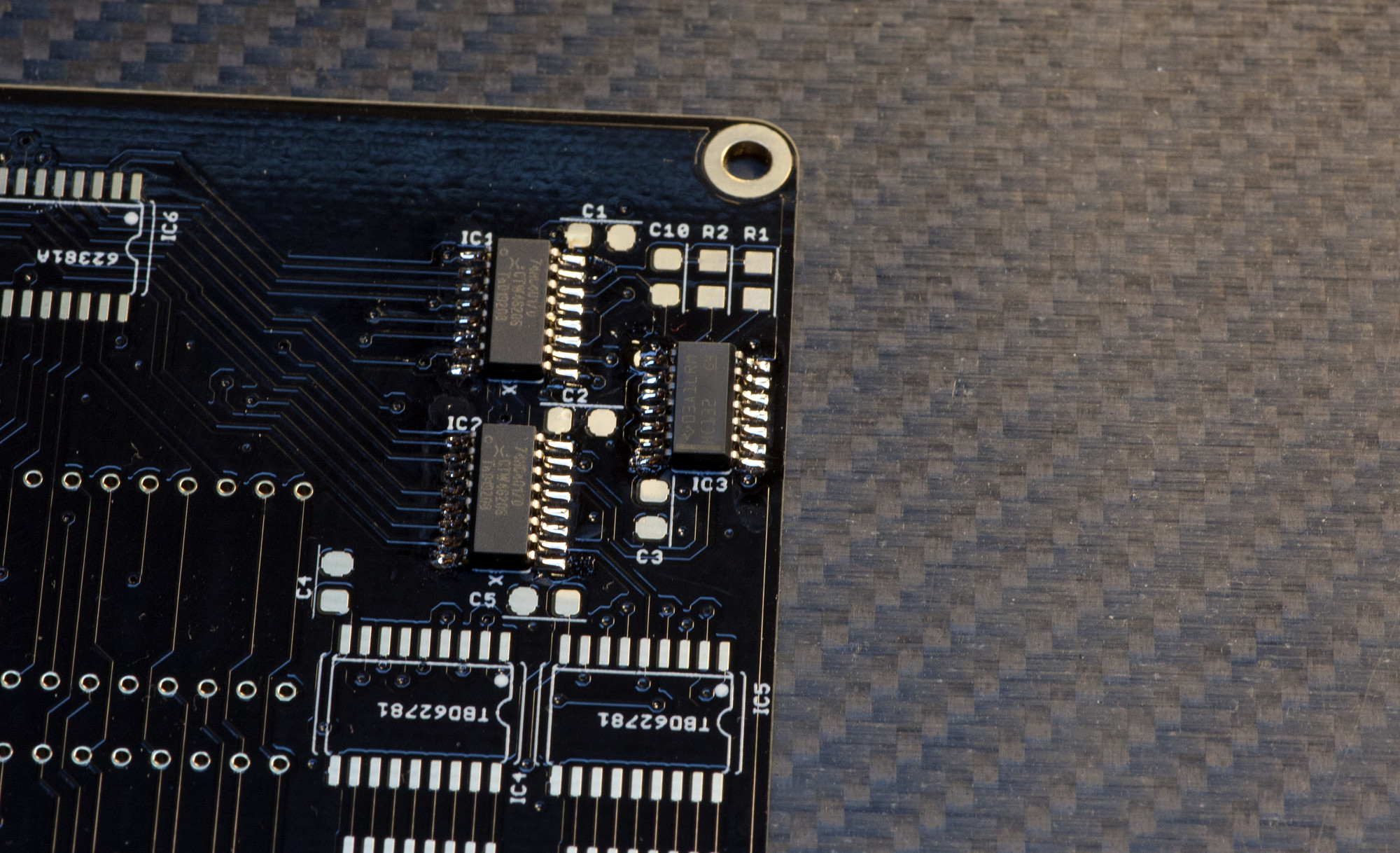
STEP 2: 74HC132D
Solder IC3 observing polarity.
Just as before - make sure the alignment is correct and check with a magnifying glass, that every pin has a good contact to the PCB and that there are no unwanted solder bridges.
Solder IC3 observing polarity.
Just as before - make sure the alignment is correct and check with a magnifying glass, that every pin has a good contact to the PCB and that there are no unwanted solder bridges.
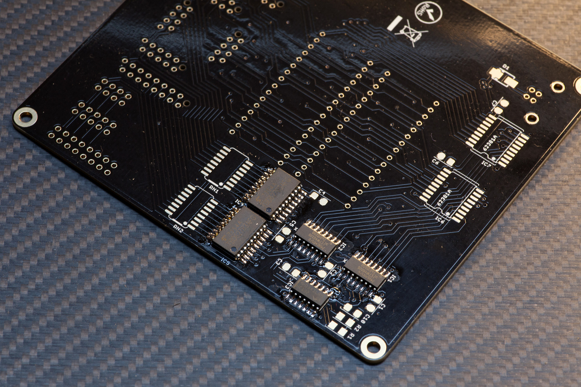
STEP 3: TBD62783
Solder IC4 and IC5 observing polarity.
Just as before - make sure the alignment is correct and check with a magnifying glass, that every pin has a good contact to the PCB and that there are no unwanted solder bridges.
Note: some PCBs have a silkscreen error, but the part TBD62783 is always correct here.
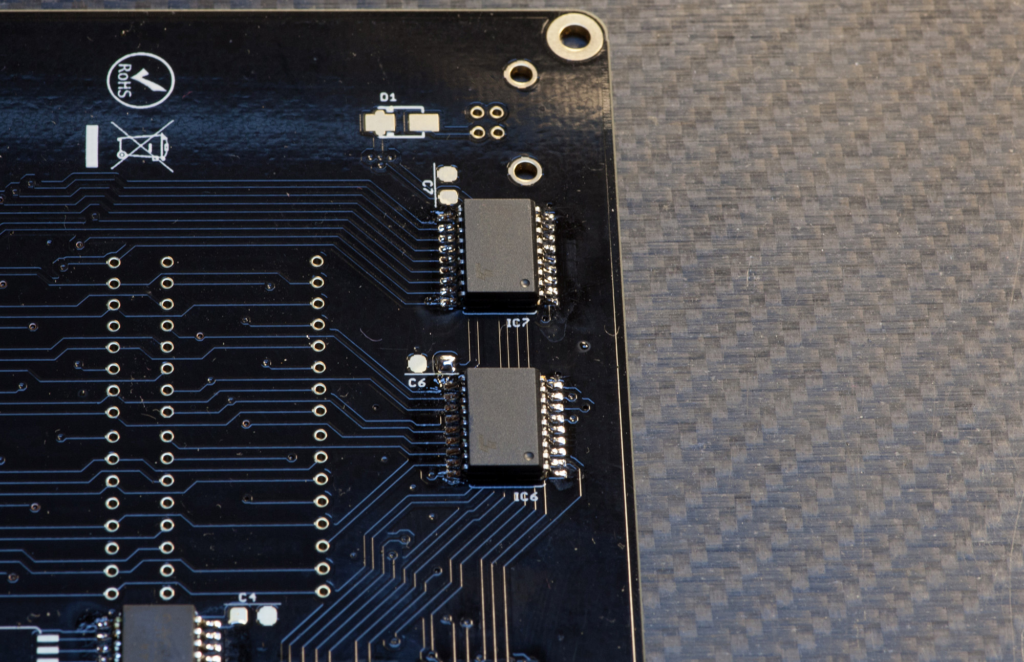
STEP 4: 62381A
Solder IC6 and IC7 observing polarity.
Just as before - make sure the alignment is correct and check with a magnifying glass, that every pin has a good contact to the PCB and that there are no unwanted solder bridges.
Solder IC6 and IC7 observing polarity.
Just as before - make sure the alignment is correct and check with a magnifying glass, that every pin has a good contact to the PCB and that there are no unwanted solder bridges.
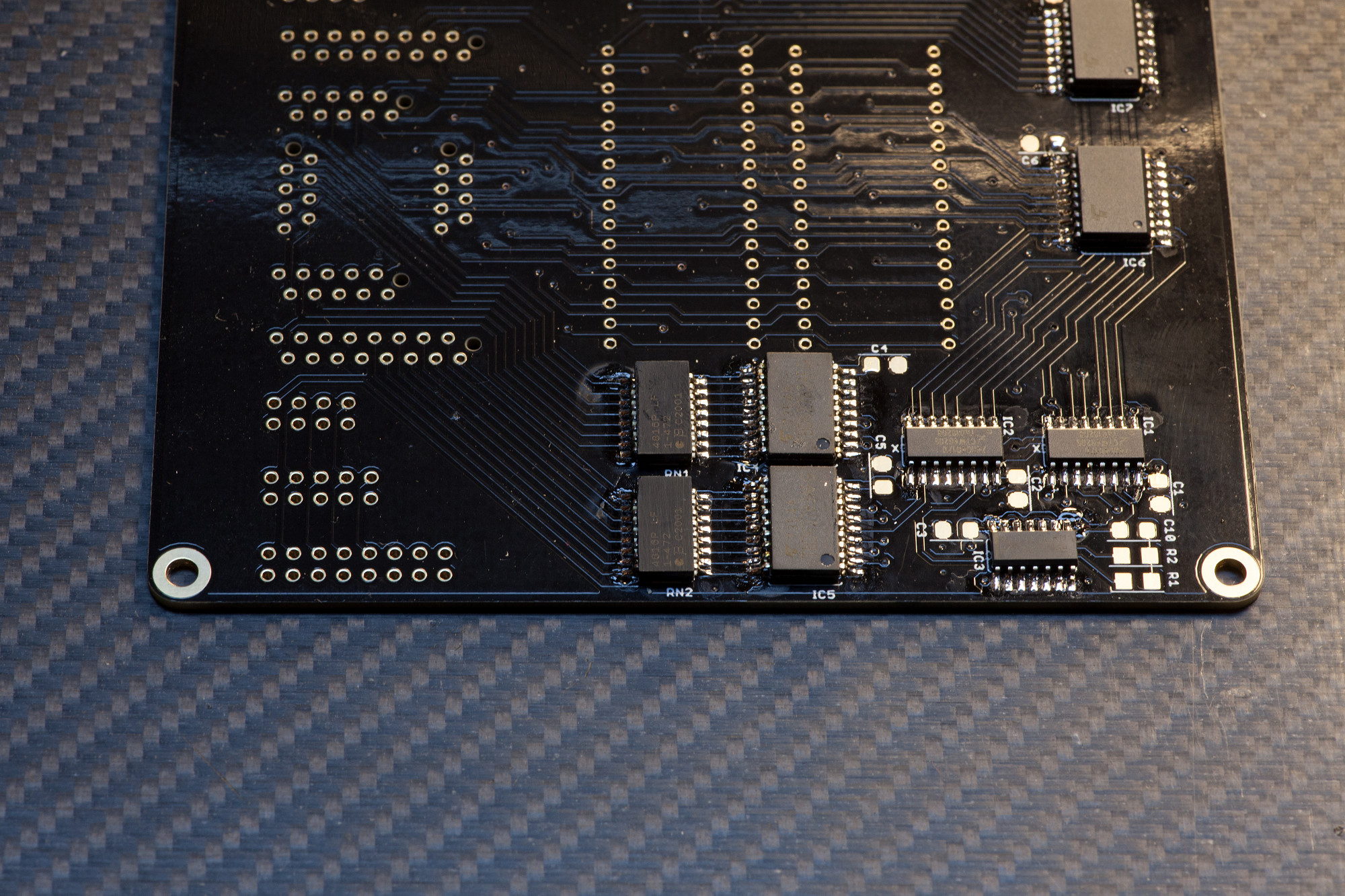
STEP 5: RESISTOR NETWORKS
Solder RN1 and RN2 observing polarity.
Just as before - make sure the alignment is correct and check with a magnifying glass, that every pin has a good contact to the PCB and that there are no unwanted solder bridges.
Solder RN1 and RN2 observing polarity.
Just as before - make sure the alignment is correct and check with a magnifying glass, that every pin has a good contact to the PCB and that there are no unwanted solder bridges.
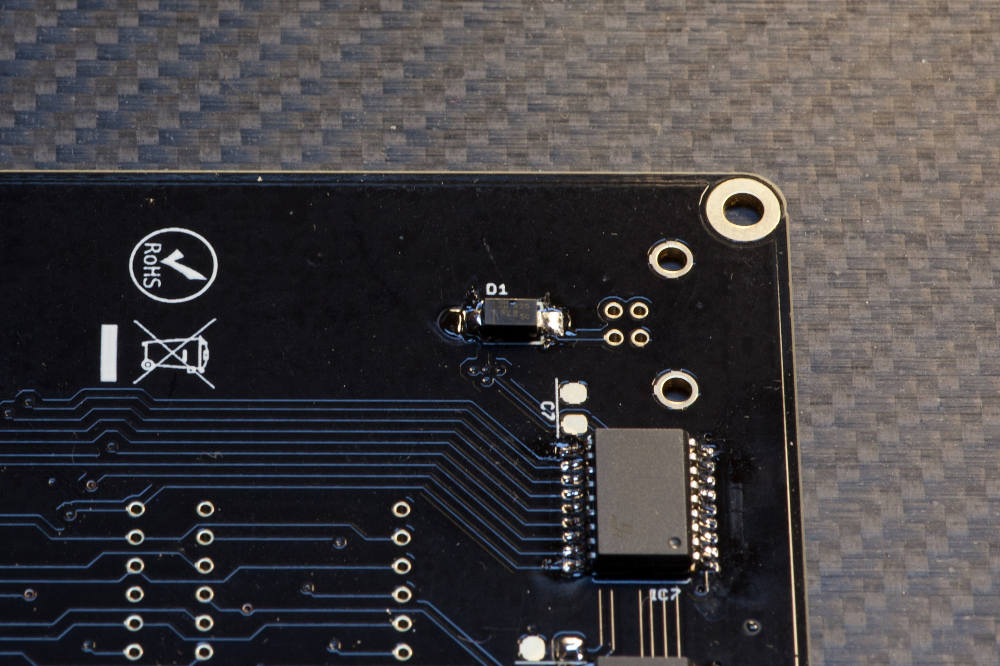
STEP 6: SMT DIODE
Solder D1 observing polarity.
Before soldering, make sure you align the line on the diode with the marking on the silkscreen.
This part is easiest soldered by tinning one pad first and then using your SMT pincers to push the SMT part on, while heating that pad. Afterwards solder the other pad. You might want to reflow the first pad you used for pushing on the part with a tiny bit of solder, if the solder point is not shiny :).
STEP 7: SMT Capacitors
Solder C1-C7, C10: these parts have no polarity, but observe different values.
These common SMT parts are easiest soldered by tinning one pad first and then using your SMT pincers to push the SMT part on, while heating that pad. Afterwards solder the other pad. You might want to reflow the first pad you used for pushing on the part with a tiny bit of solder, if the solder point is not shiny :).
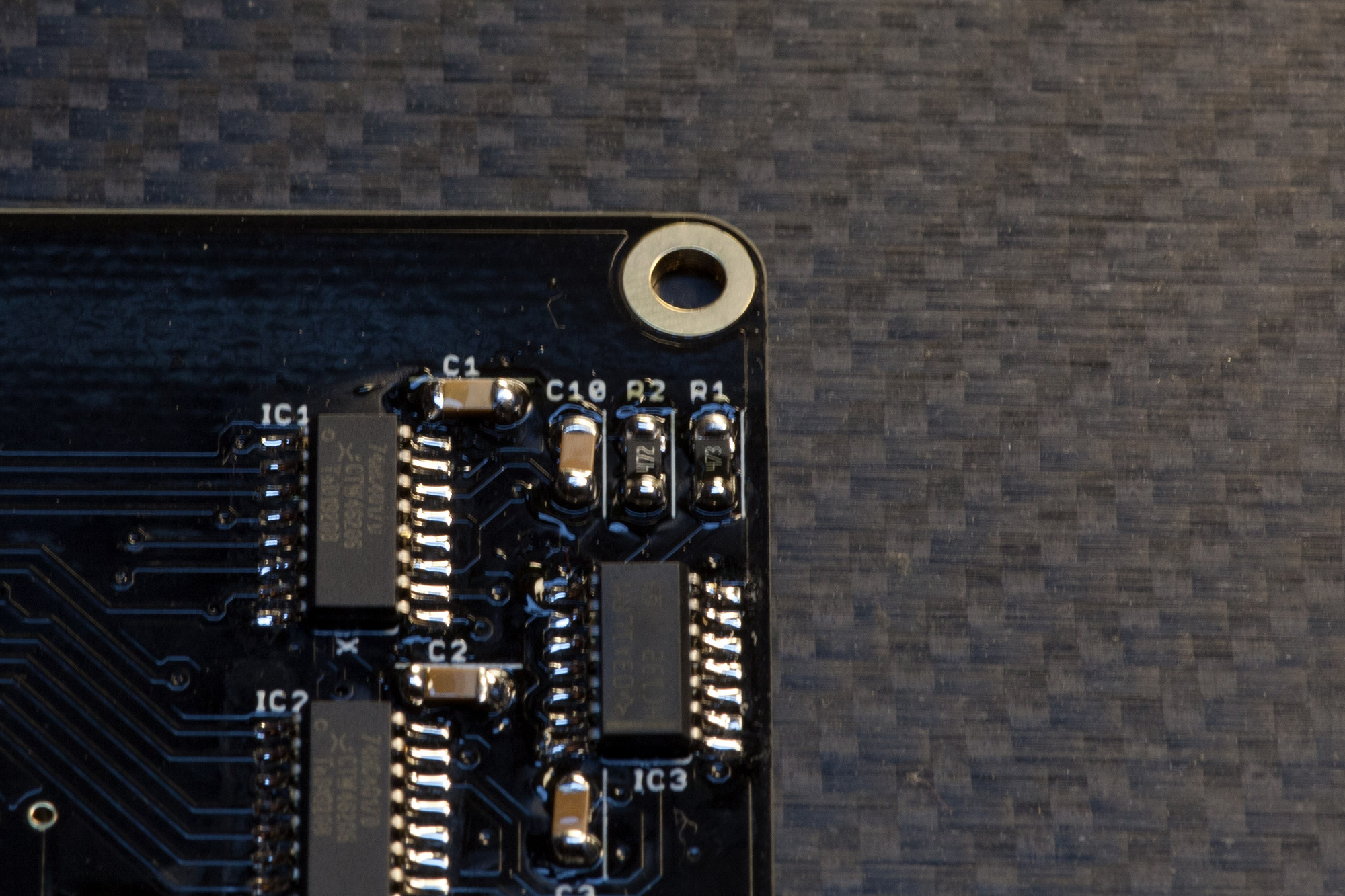
STEP 8: SMT Resistors
Solder R1 and R2: these parts have no polarity, but observe different values.
These common SMT parts are most easily soldered by tinning one pad first and then using your SMT pincers to push the SMT part on, while heating that pad. Afterwards solder the other pad. You might want to reflow the first pad you used for pushing on the part with a tiny bit of solder, if the solder point is not shiny :).
STEP 9: LED MATRICES
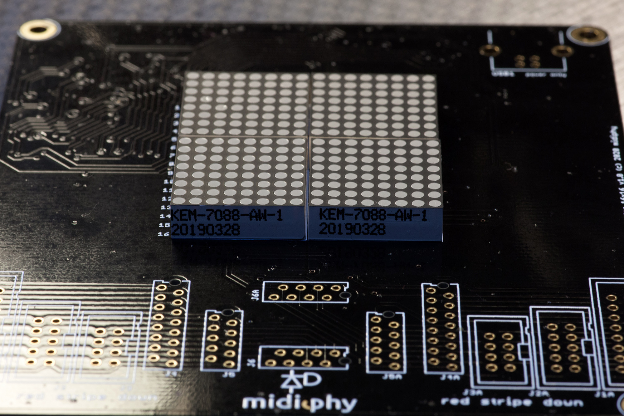
Solder MATRIX1-4, observing polarity
Take care to align the LED rows and columns as straight as possible. This is most easily done by inserting all four 8x8 matrices and soldering one pin of each, then verifying alignment before proceeding with the other pins.
Align the printed text on the LED matrices (indicating the side with pin 1 on the left) with the marking on the PCB - as shown in the picture. Clip off all remaining THT pins afterwards.
STEP 10: USB POWER PORT
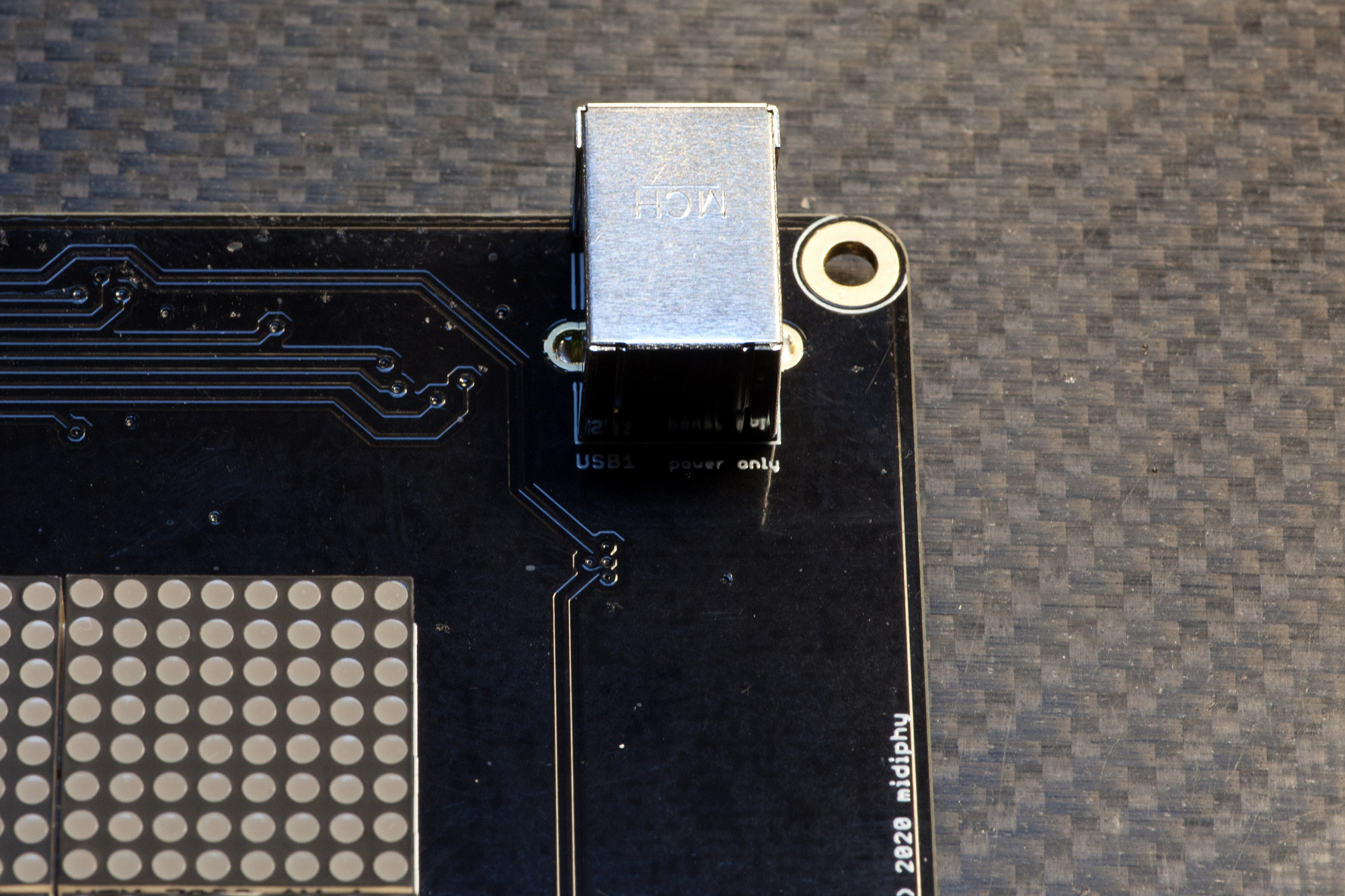
Solder USB1
This port is only used for powering the midiphy wirescanner - make sure you solder the stabilizing pins properly.
Solder USB1
This port is only used for powering the midiphy wirescanner - make sure you solder the stabilizing pins properly.
STEP 11: Solder IDC and Micromatch connectors
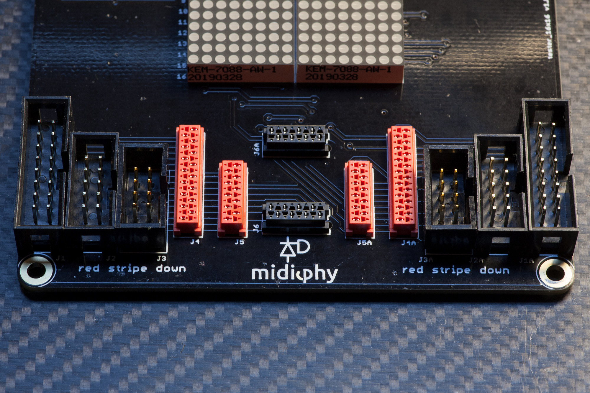
Solder J1(A)-J6(A)
Make sure you align the IDC shrouded header notches with the notches on the PCB silkscreen.
Note that the image depicts an older PCB version with one extra set of micromatch connectors. Newer versions lack these.
Solder J1(A)-J6(A)
Make sure you align the IDC shrouded header notches with the notches on the PCB silkscreen.
Note that the image depicts an older PCB version with one extra set of micromatch connectors. Newer versions lack these.
Done! :)
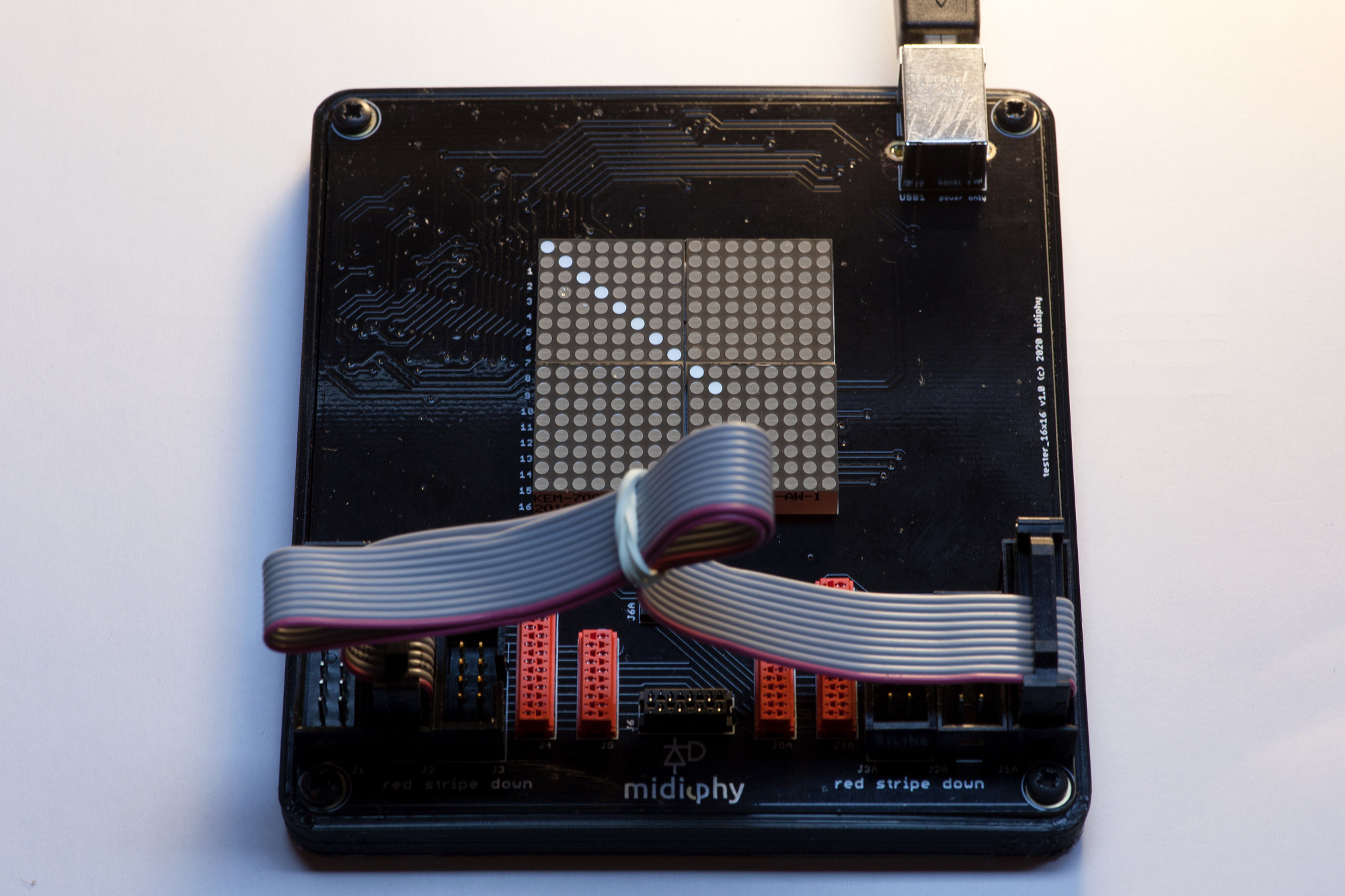
If you have a midiphy wirescanner shell case, you can fasten it with the four supplied screws, but you can also use the wirescanner PCB stand-alone.
Now power via USB and enjoy cable-testing! :)
If you have a midiphy wirescanner shell case, you can fasten it with the four supplied screws, but you can also use the wirescanner PCB stand-alone.
Now power via USB and enjoy cable-testing! :)