product details
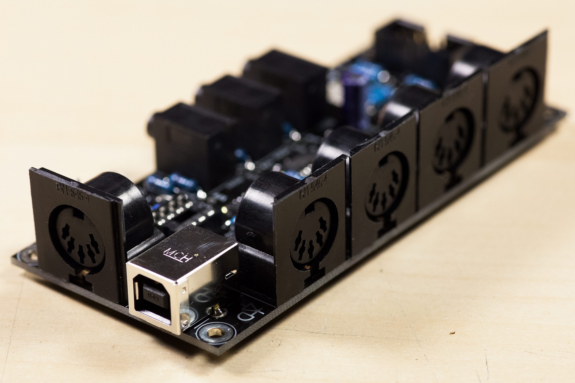
MULTI MIDI THRU PCB (Revision A)
Product ID: P-UTL-01
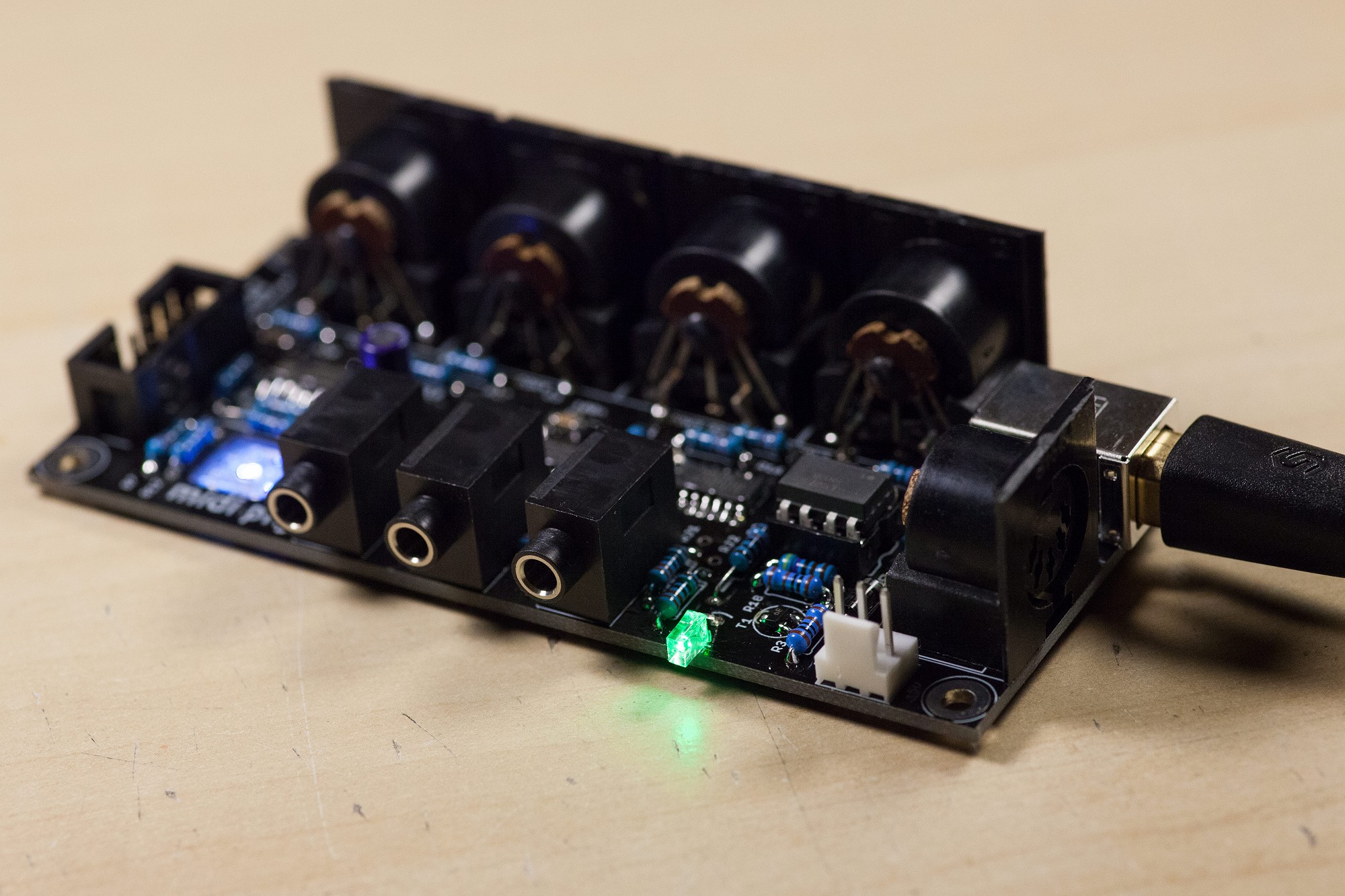
USB-powered quad DIN + triple 3.5mm MIDI thru board. Chainable for 8xDIN, 6x3.5mm, perfect for low-latency MIDI to multiple synthesizers and SMT soldering training.
Weight: 35 grams
NEW AND IMPROVED VERSION AVAILABLE! -> Search for P-UTL-01B (MULTI MIDI THRU PCB, Revision B)
Bill of Materials / Placement Guide
Label
Package
Name
Side
Part Link
Notes
Required Mouser parts
Can be directly transferred into your
mouser cart by copying & pasting the text below into the mouser part list import tool (you
may need to log in at mouser before the tool is available):
https://www.mouser.com/tools/part-list-import.aspx
https://www.mouser.com/tools/part-list-import.aspx
80-C1206C104M5R|4
667-ECA-1HM330I|1
806-KCDX-5S-S2|5
511-1N5817|1
512-1N4148TR|1
512-6N138M|1
517-4808-3004-CP|1
771-74HC14D-T|2
595-SN74HC595DR|1
710-61201021621|2
490-SJ1-3535NG|3
604-WP914HDT|1
749-R50RGB-F-0160|1
660-MF1/4DCT52R2200F|17
660-MF1/4DCT52R1002F|4
660-MF1/4DCT52R1001F|2
652-CRM1206QJW-103E|2
660-MF1/4DCT52R4701F|1
863-BC818-40LT1G|1
538-67068-8000|1
The BOM checker 'bot says:
All parts referenced from the CAD master files have been validated. The BOM should be safe to order!*
* Disclaimer: although we have taken the best care possible, we cannot guarantee 100%
accuracy and we cannot be held liable for erroneous orders when using
this tool, including (but not limited to) incorrect quantities and/or
types of components ordered through midiphy or other suppliers.
Recommended products
These additional products may be of interest:
Photo Tutorial
Step 1
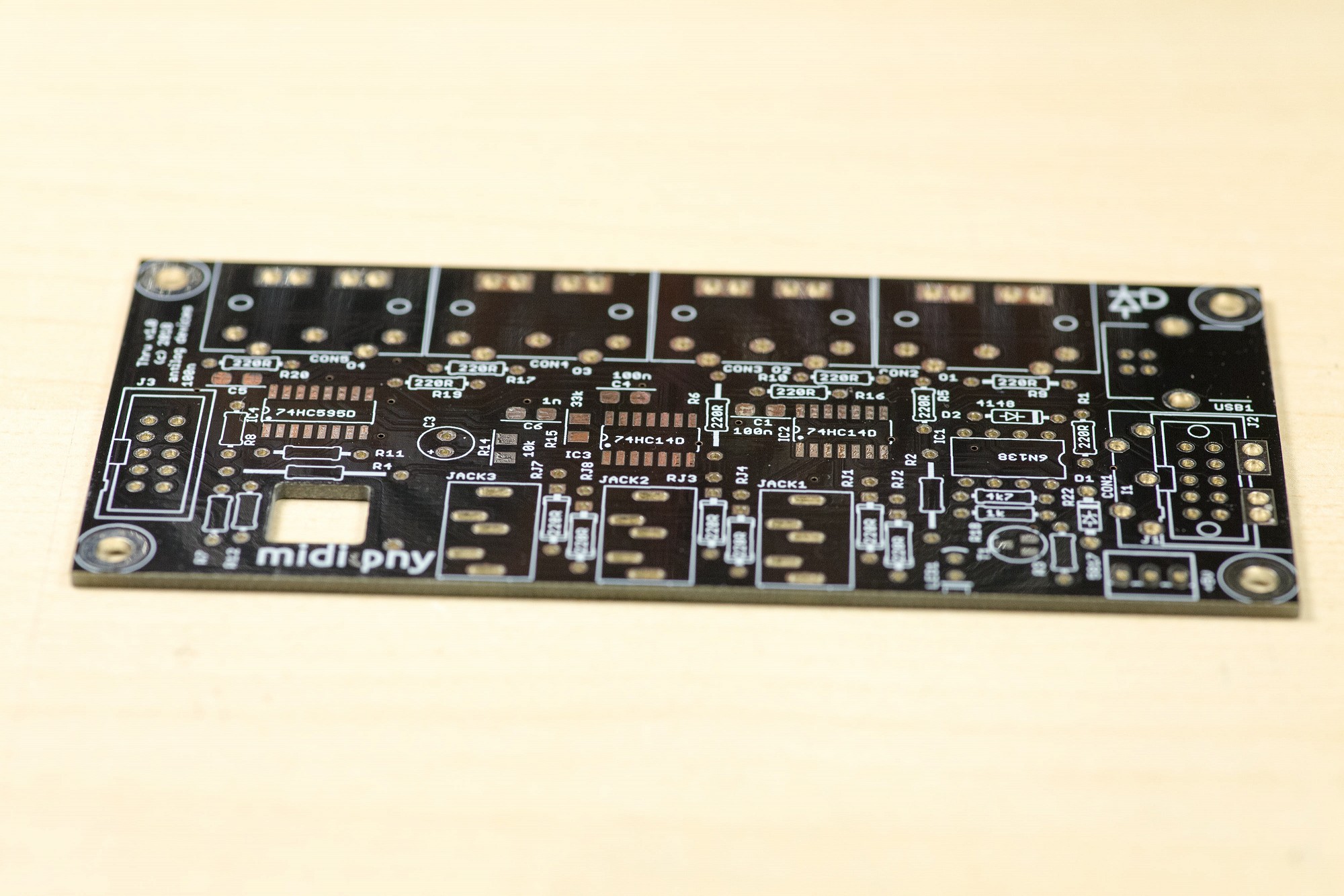
Let's build the MULTI MIDI THRU PCB!
It will be a good SMT soldering exercise and contains many relevant parts used in more complex midiphy projects.
It will also be a very helpful tool in your MIDI studio. The MULTI MIDI THRU allows to connect:
up to four standard DIN MIDI devices/synthesizers
up to three modern TRS (3.5mm jack) MIDI devices
You could also chain two MULTI MIDI THRU boards (perhaps more!) using the onboard shrouded headers for eight + six MIDI THRUs with minimal latency.
Step 2
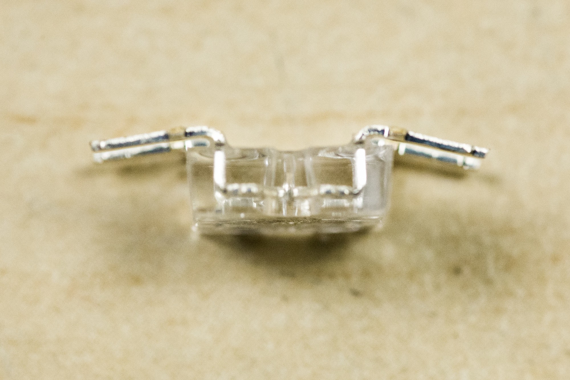
First, bend the superflux LED pins into a gullwing shape as shown. Ensure that you use an ESD antistatic wriststrap to ground yourself before working with the LED. It's best to bend using a tool like a flat-head screwdriver to avoid straining the bond wires within the LED.
First, bend the superflux LED pins into a gullwing shape as shown. Ensure that you use an ESD antistatic wriststrap to ground yourself before working with the LED. It's best to bend using a tool like a flat-head screwdriver to avoid straining the bond wires within the LED.
Step 3
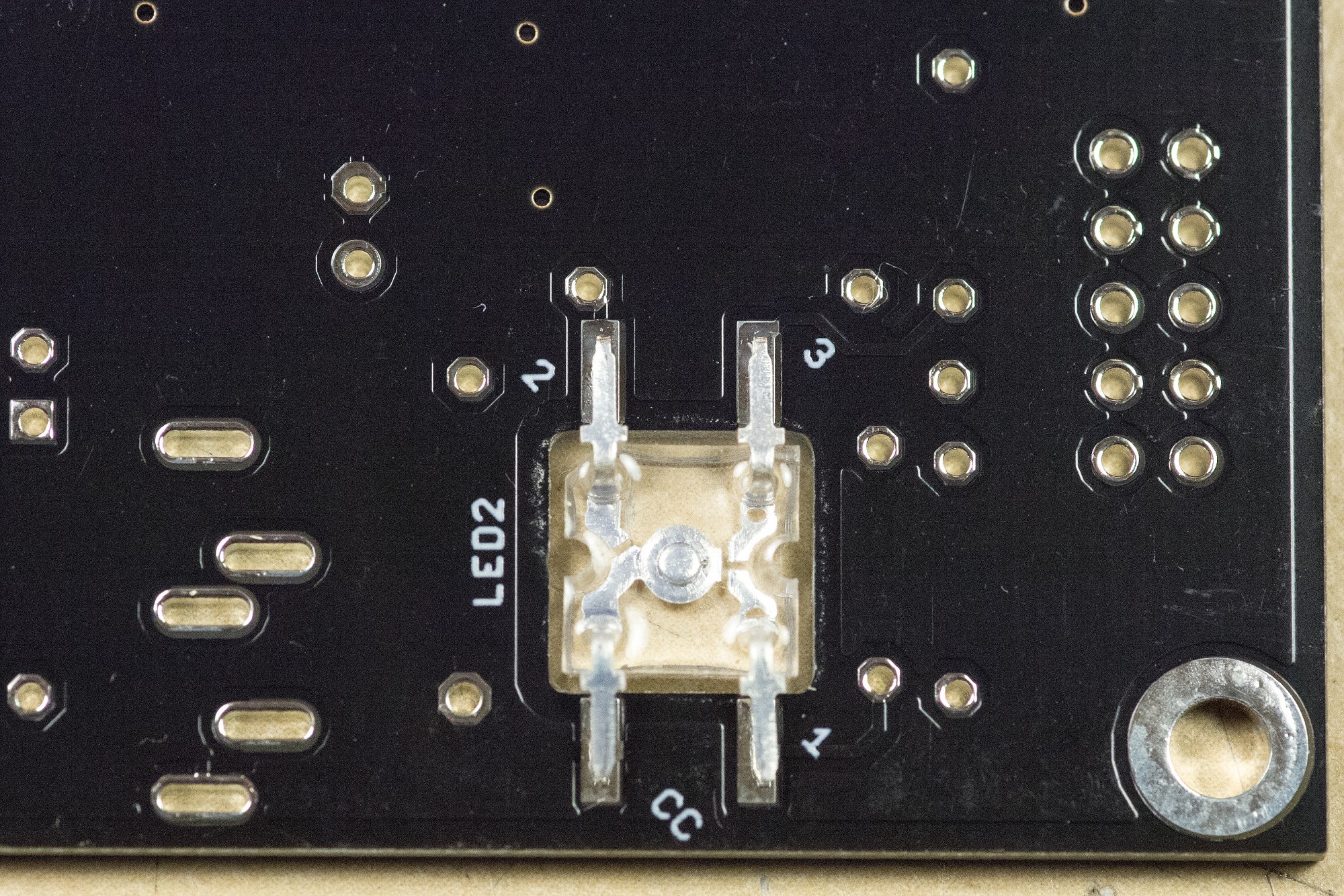
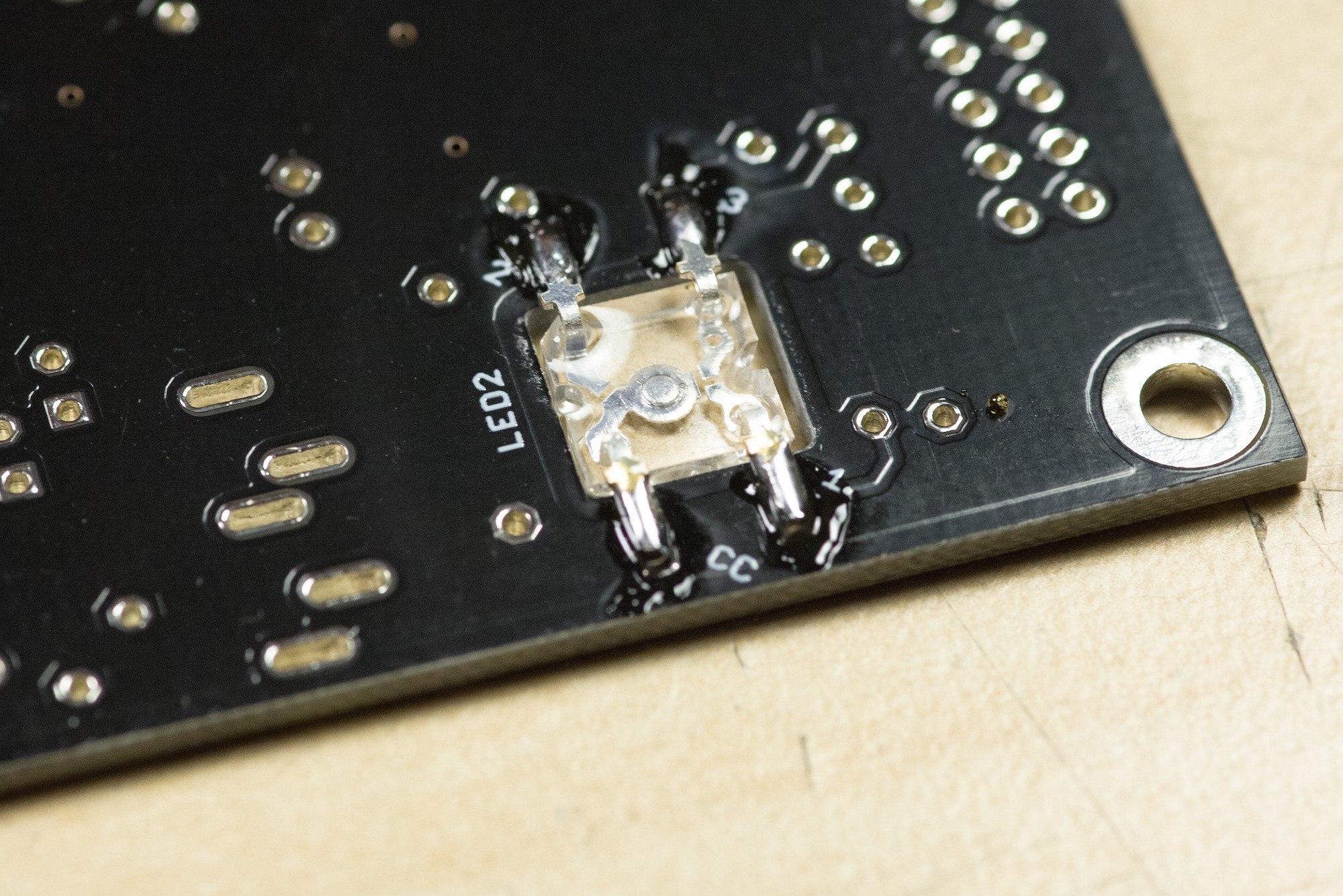
Insert the LED as shown on the rear of the PCB. Note that the common cathode pin within the acrylic package is physically larger than the three anodes and connects to the LED center. This can be verified with a digital multimeter in diode mode: the LED colors should light up when the black probe (-) is on the cathode. Check that the bent gullwing leg goes to the lower-left pin marked as "CC", not to pin 3 in the opposite corner!
Insert the LED as shown on the rear of the PCB. Note that the common cathode pin within the acrylic package is physically larger than the three anodes and connects to the LED center. This can be verified with a digital multimeter in diode mode: the LED colors should light up when the black probe (-) is on the cathode. Check that the bent gullwing leg goes to the lower-left pin marked as "CC", not to pin 3 in the opposite corner!
Step 4
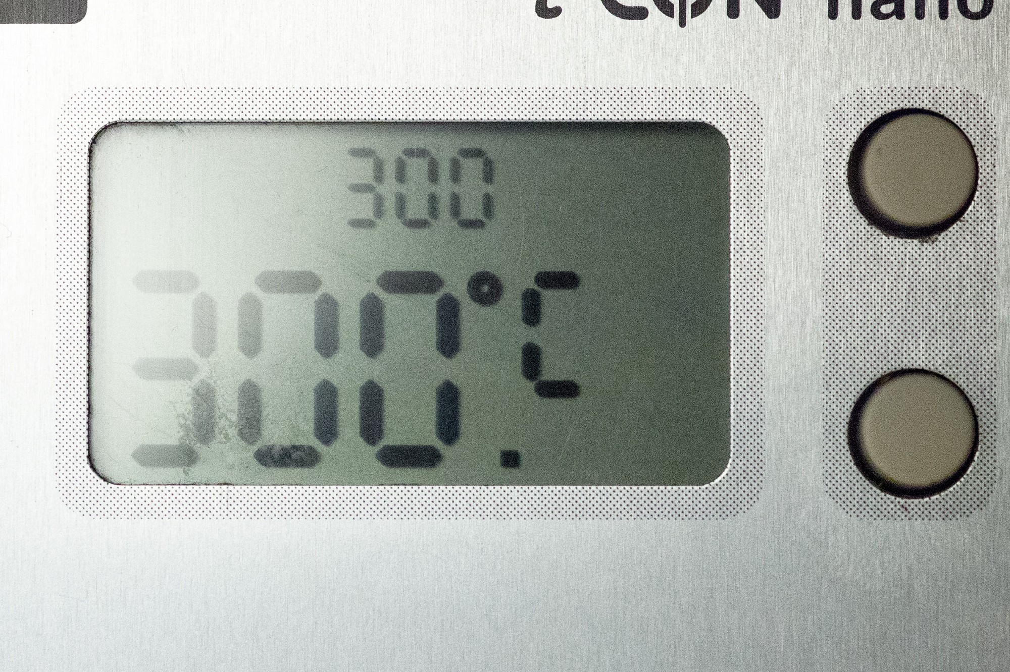
Set your soldering iron to 300°C and heat the PCB pad first (not the LED pins) when soldering the superflux LED. Solder for only two or three seconds to avoid overheating the LED.
Set your soldering iron to 300°C and heat the PCB pad first (not the LED pins) when soldering the superflux LED. Solder for only two or three seconds to avoid overheating the LED.
Step 5
That's how the superflux LED should look after soldering. Note that when building other midiphy projects, the common pin will sometimes be bent differently or soldered in later.
That's how the superflux LED should look after soldering. Note that when building other midiphy projects, the common pin will sometimes be bent differently or soldered in later.
Step 6
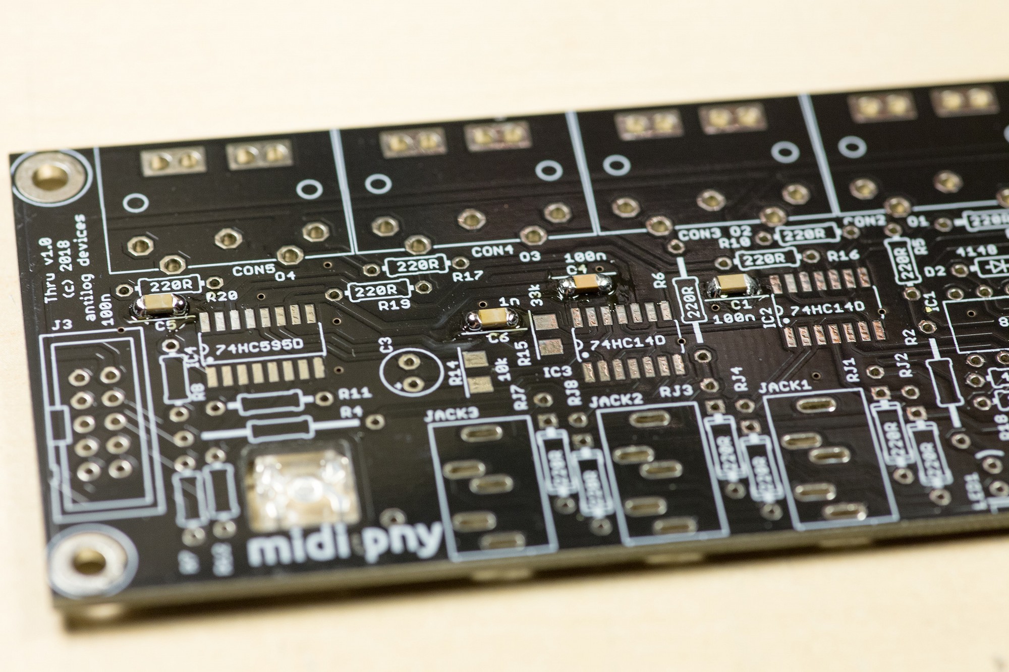
Solder 100nF 1206 SMT capacitors in C1, C4, C5, C6. Disregard any "1n" silkscreen label for C6, it should be a 100nF cap.
Solder 100nF 1206 SMT capacitors in C1, C4, C5, C6. Disregard any "1n" silkscreen label for C6, it should be a 100nF cap.
Step 7
Solder T1, the BC818 SMT transistor.
Solder T1, the BC818 SMT transistor.
Step 8
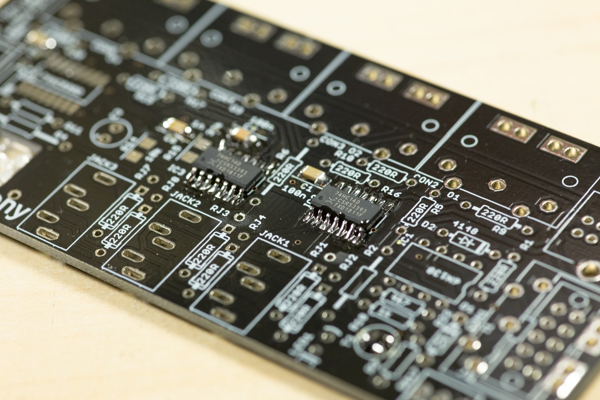
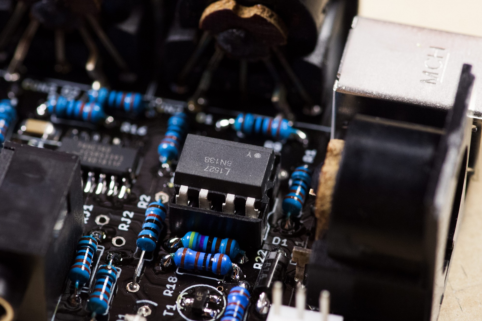
Solder IC2 and IC3, the 74HC14D hexinverters. A good practice is to tack one of the corner pins and then correct the position before completing the other pins. Visually check for good solder joints that bond the pin to the pad and also check for unwanted shorts between adjacent pins with a magnifying glass. If there are problems, they are easy to fix now, but it gets more difficult once the DIN sockets are installed.
Solder IC2 and IC3, the 74HC14D hexinverters. A good practice is to tack one of the corner pins and then correct the position before completing the other pins. Visually check for good solder joints that bond the pin to the pad and also check for unwanted shorts between adjacent pins with a magnifying glass. If there are problems, they are easy to fix now, but it gets more difficult once the DIN sockets are installed.
Step 9
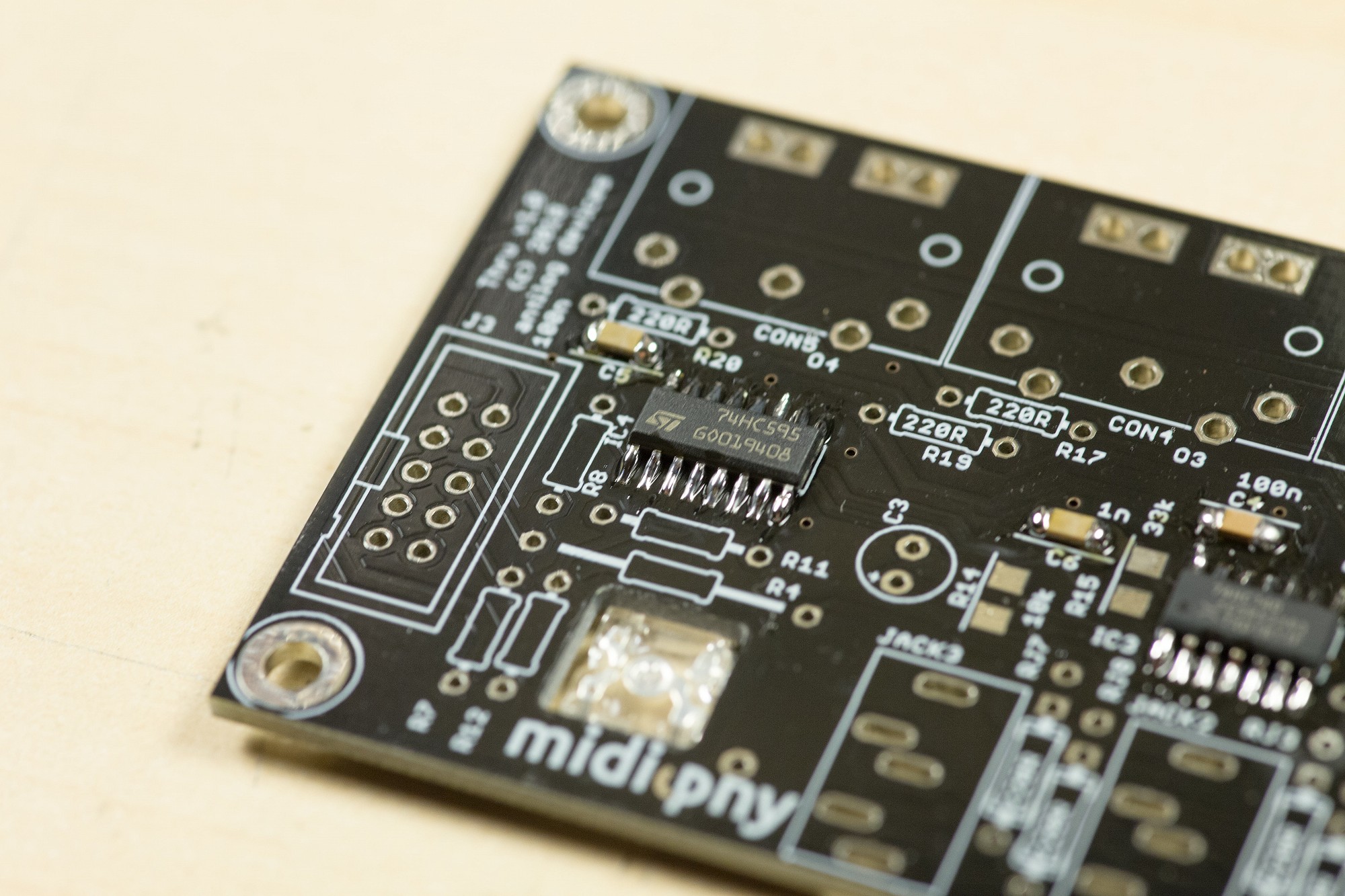
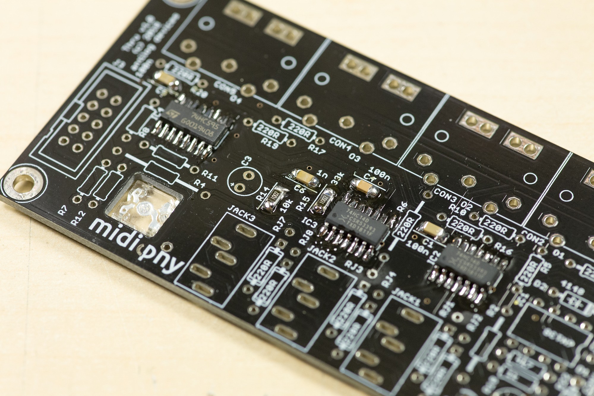
Install the 74HC595D output shift register in IC4. As noted in the previous step, check all pins with a magnifying glass before continuing with the next step.
Install the 74HC595D output shift register in IC4. As noted in the previous step, check all pins with a magnifying glass before continuing with the next step.
Step 10
Install R14 and R15 - use 10k 1206 resistors and disregard other value indicators.
Note:
If you want quicker superflux LED MIDI data indication, replace R15 with a 1k resistor. This will speed up the superflux update rate from ~3Hz to ~30Hz.
Install R14 and R15 - use 10k 1206 resistors and disregard other value indicators.
Note:
If you want quicker superflux LED MIDI data indication, replace R15 with a 1k resistor. This will speed up the superflux update rate from ~3Hz to ~30Hz.
Step 11
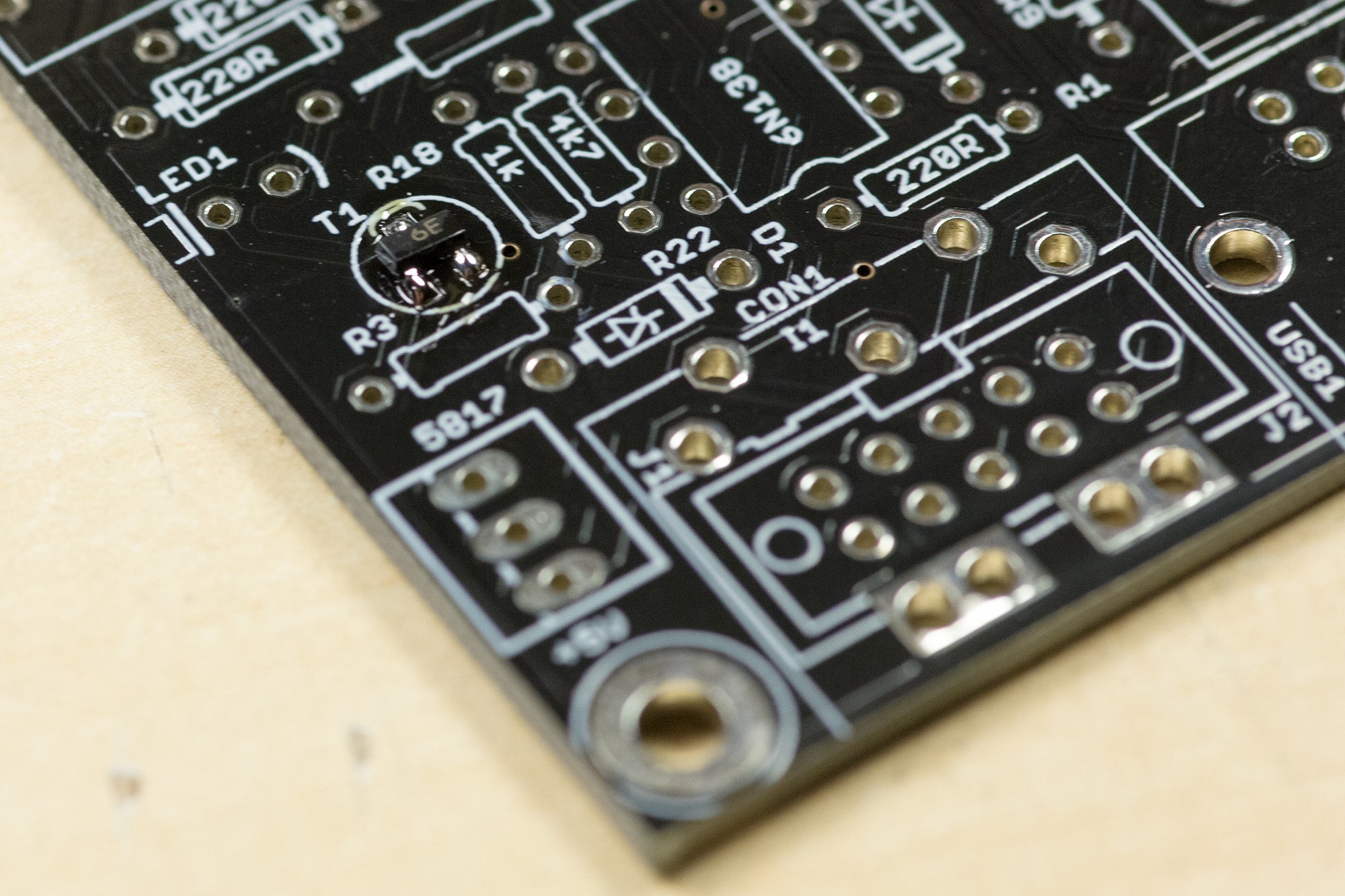
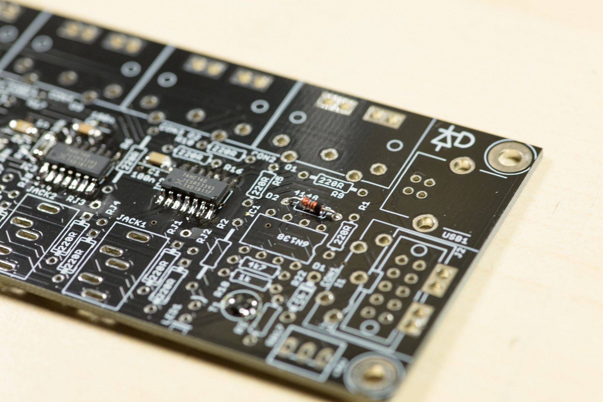
Install D2, a standard 1N4148 THT diode.
Install D2, a standard 1N4148 THT diode.
Step 12
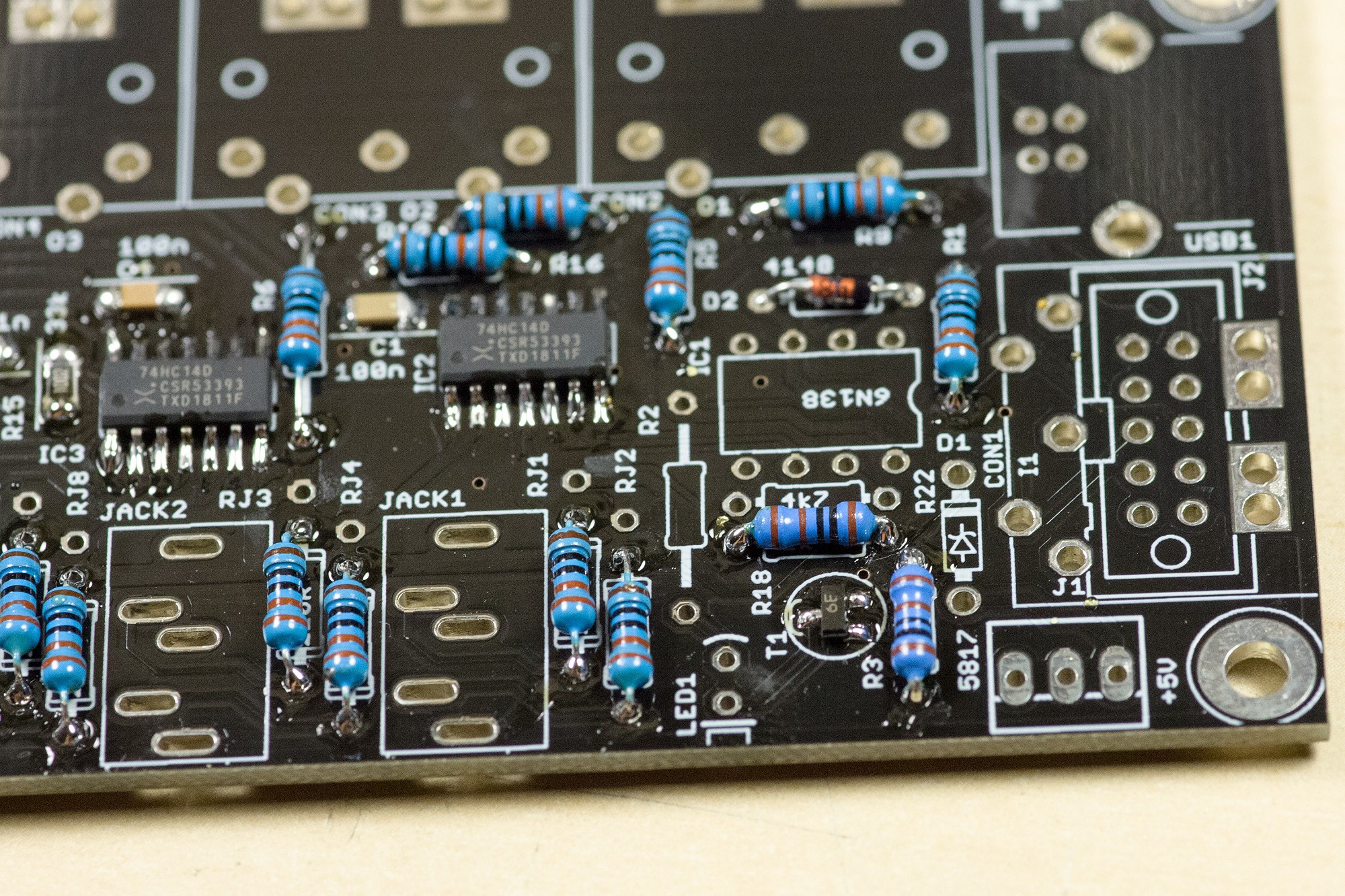
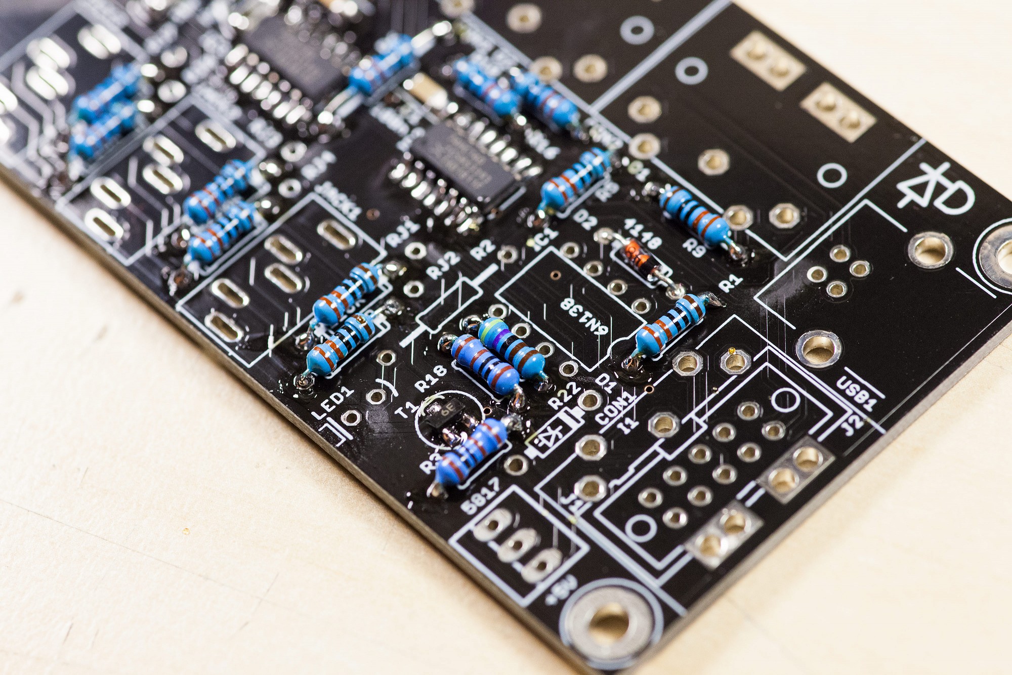
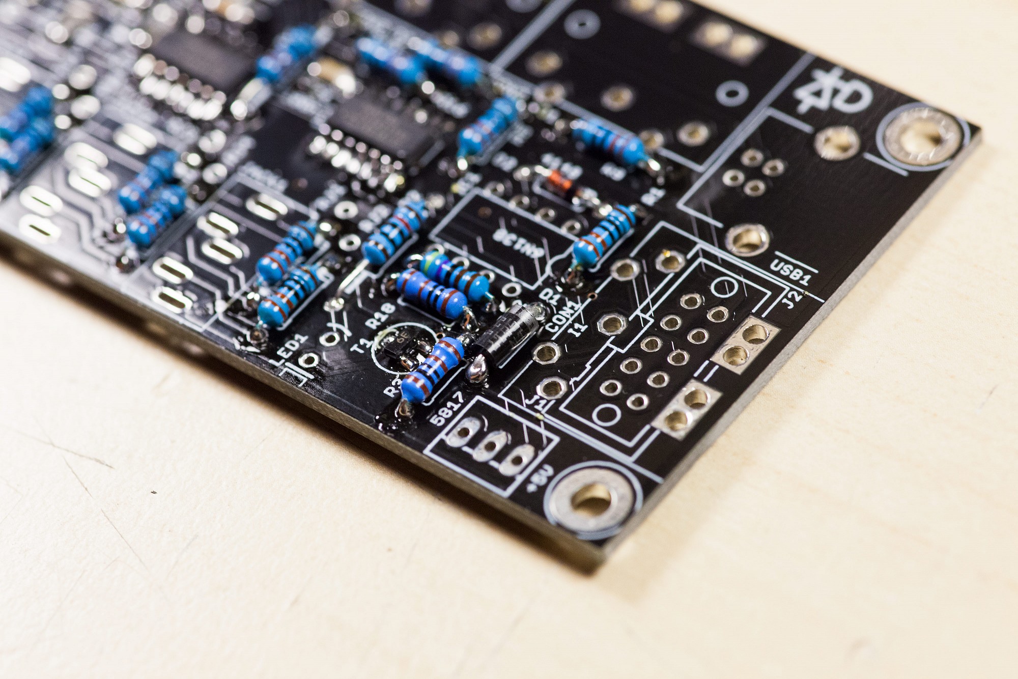
Install 220R THT resistors in R1, R4, R5, R6, R7, R9, R10, R16, R17, R19, R20, RJ1, RJ2, RJ3, RJ4, RJ7, RJ8.
There are two known implementations for TRS MIDI:
For the "Korg" standard (Type A), use the round solder pads for RJs.
For the "Arturia" standard (Type B), use the square solder pads for RJs.
The MMA has adopted "Type A" as a standard for the MIDI specification, so in case of doubt, it is probably advisable to use this variant.
Mixing the two standards is possible as long as each pair of RJs uses the a single configuration.
Step 13
Install 1K THT resistors in R3 and R18.
Install 1K THT resistors in R3 and R18.
Step 14
Install a 4k7 THT resistor in R22.
Install a 4k7 THT resistor in R22.
Step 15
Install 10k THT resistors in R2, R8, R11 and R12.
Install 10k THT resistors in R2, R8, R11 and R12.
Step 16 - optional
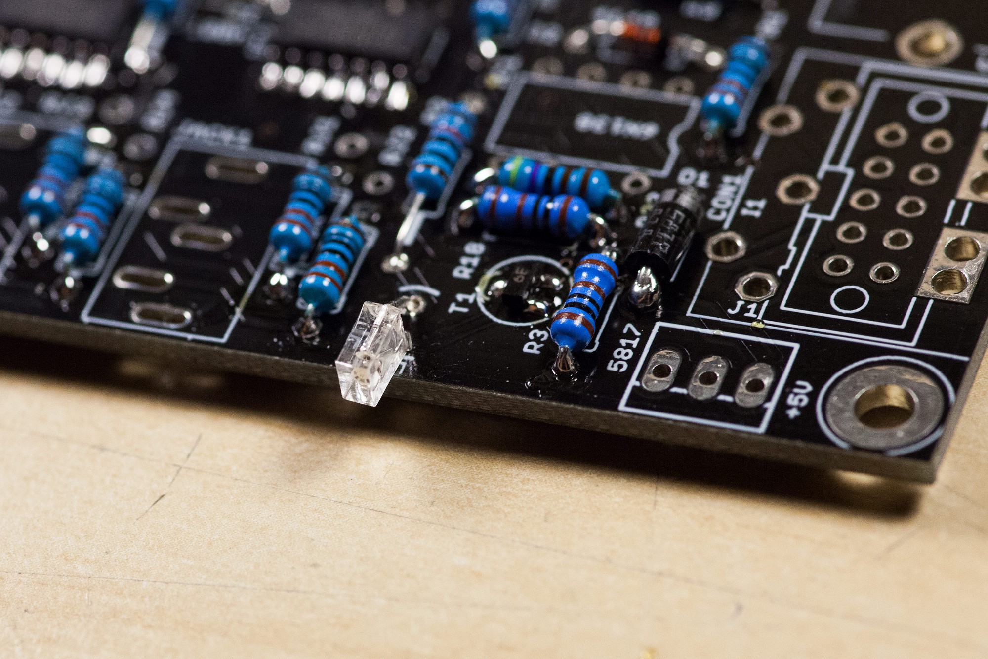
Install the 1N5817 "reverse polarity protection" diode in D1 if you plan to use the J1 power header.
Install the 1N5817 "reverse polarity protection" diode in D1 if you plan to use the J1 power header.
Step 17
Install the 2x3x4mm LED as shown.
The longer LED leg is the anode and goes into the rear pad marked with a curve on the PCB. The pad close to the PCB edge is the cathode and is marked with a flat line - the shorter LED leg goes in there.
Install the 2x3x4mm LED as shown.
The longer LED leg is the anode and goes into the rear pad marked with a curve on the PCB. The pad close to the PCB edge is the cathode and is marked with a flat line - the shorter LED leg goes in there.
Step 18
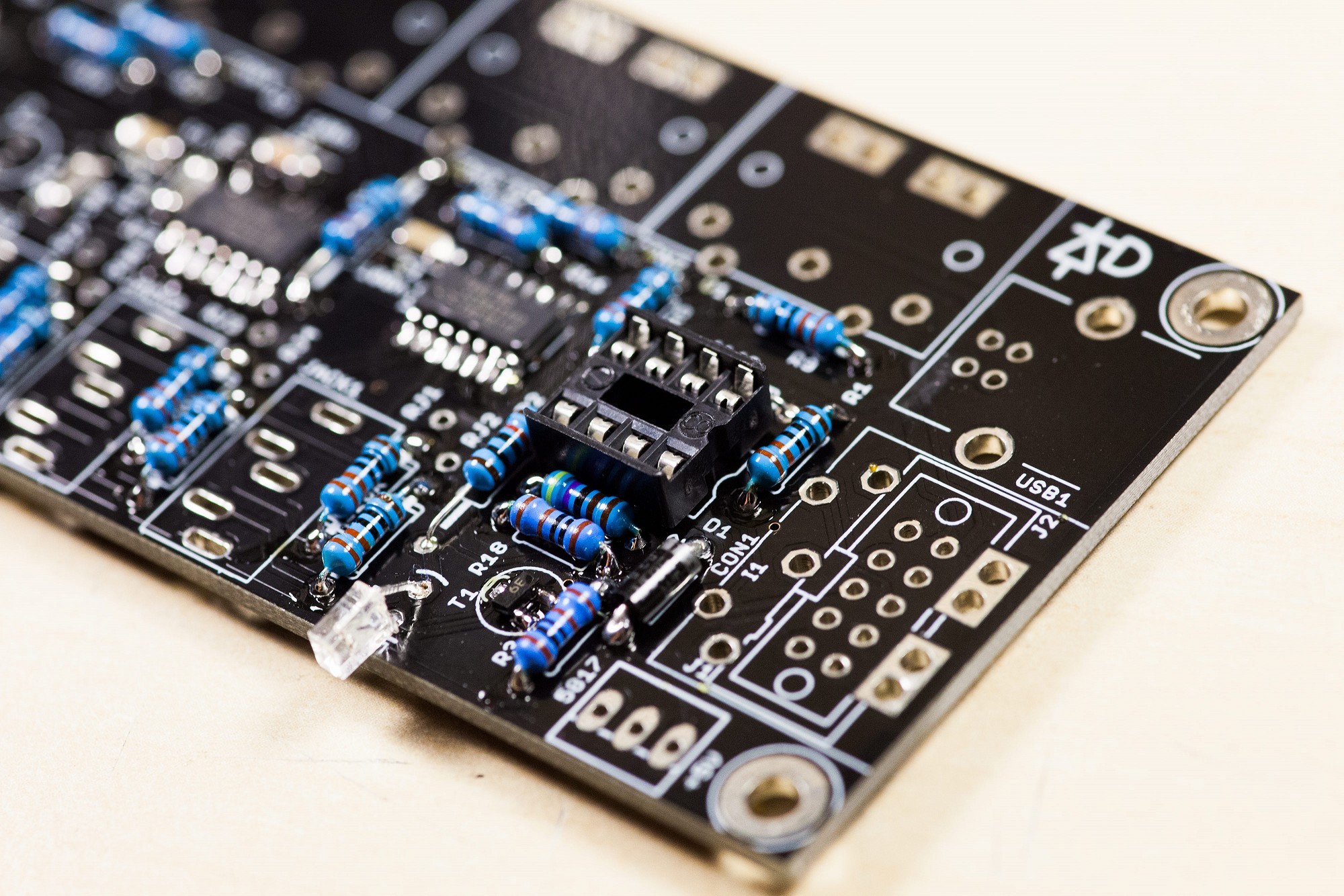
Install the 8-pin IC socket for IC1. Align the notch of the IC socket with the notch on the PCB silkscreen.
Install the 8-pin IC socket for IC1. Align the notch of the IC socket with the notch on the PCB silkscreen.
Step 19
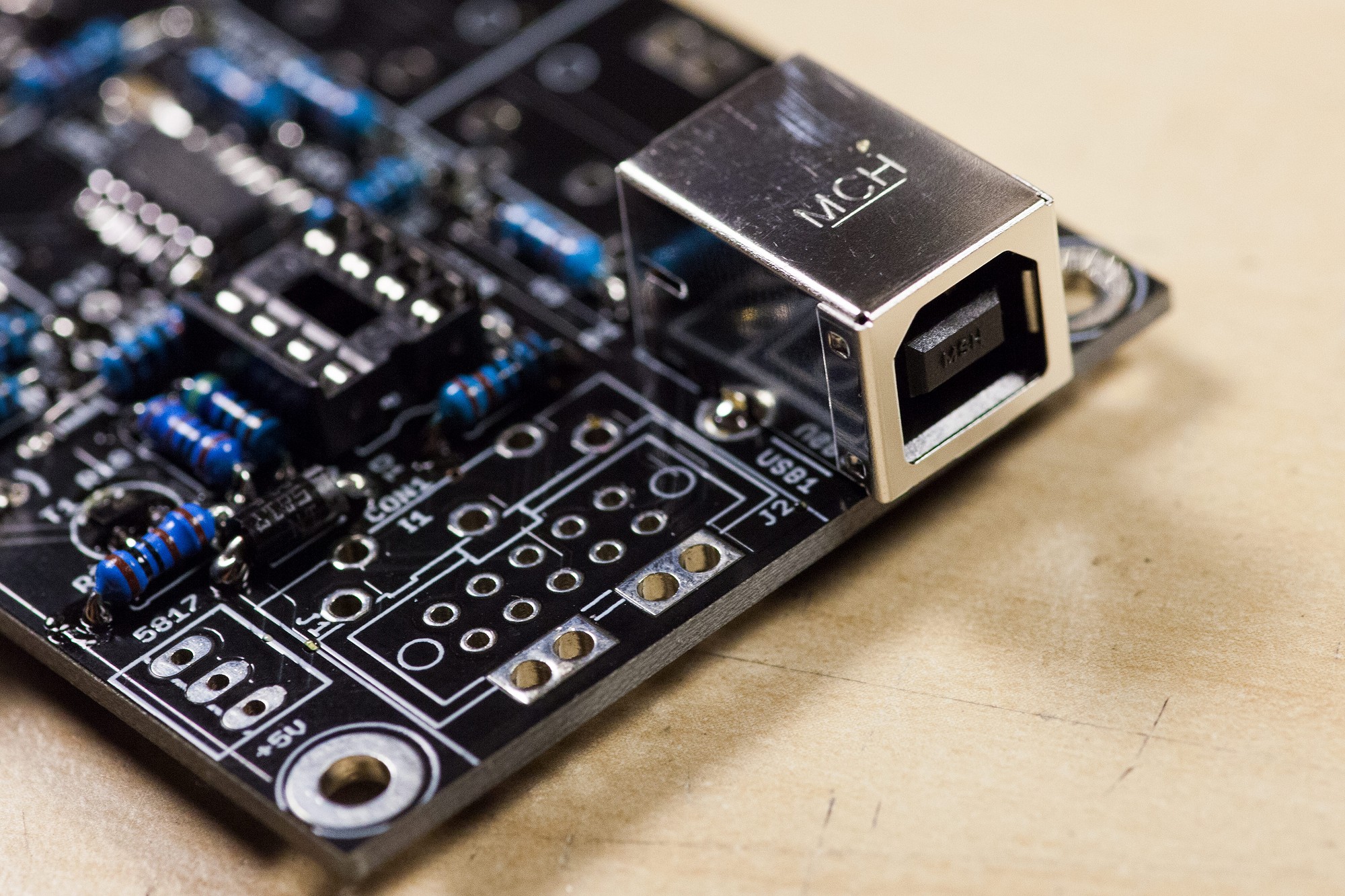
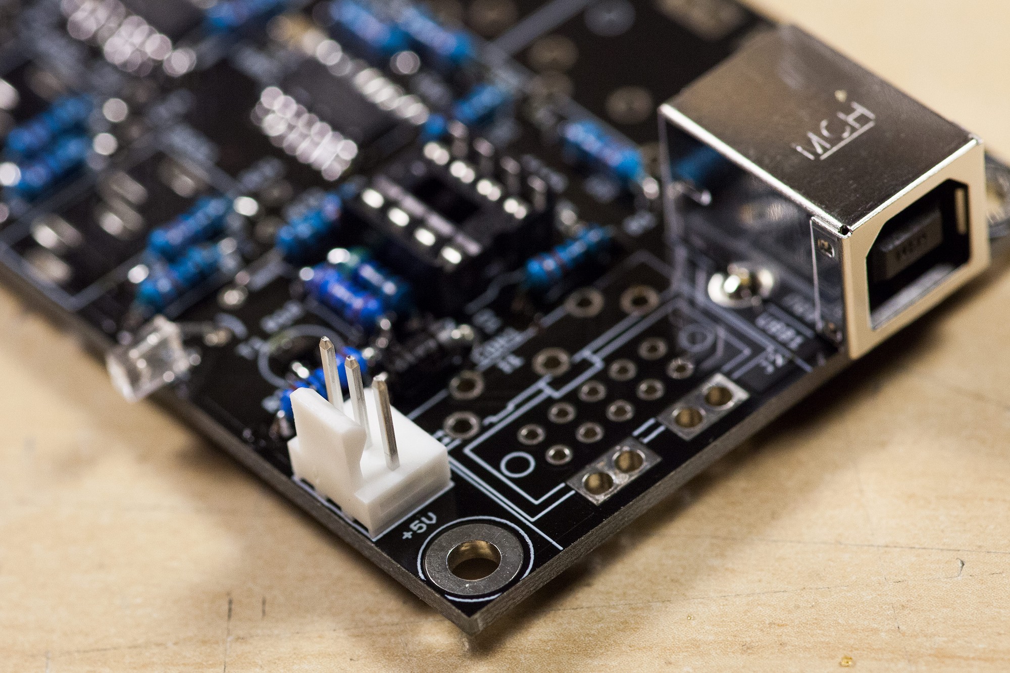
Install the USB socket at "USB1".
Install the USB socket at "USB1".
Step 20 - optional
Install the 3-pin header close to the bottom of the board. You can use this header to supply 5V to the PCB instead of using the USB port for power.
Install the 3-pin header close to the bottom of the board. You can use this header to supply 5V to the PCB instead of using the USB port for power.
Step 21 - optional
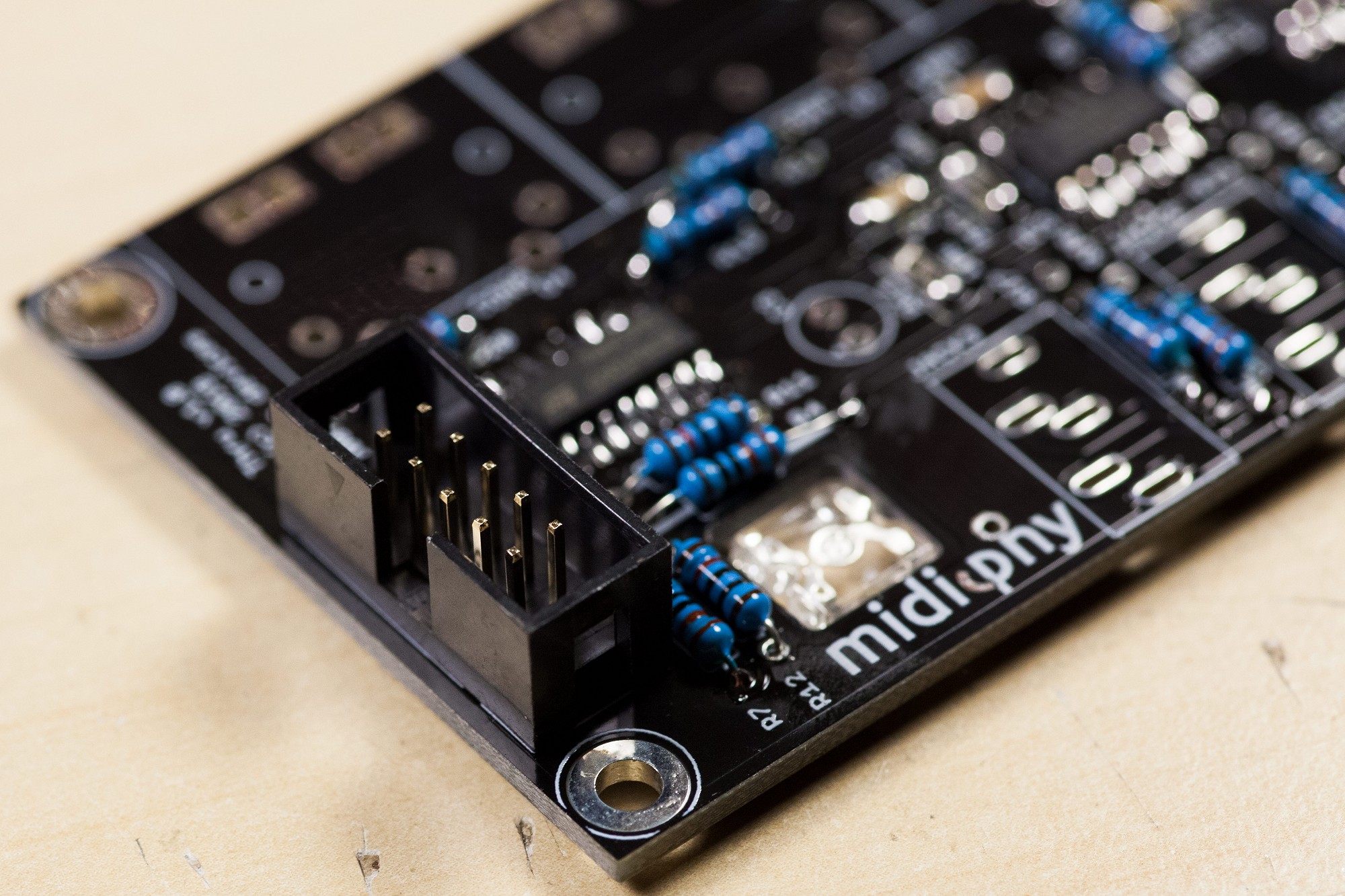
Install the 2x5pin shrouded header on J3.
You only need to install it if you want to chain two (or more) MULTI MIDI THRU PCBs.
Install the 2x5pin shrouded header on J3.
You only need to install it if you want to chain two (or more) MULTI MIDI THRU PCBs.
Step 22
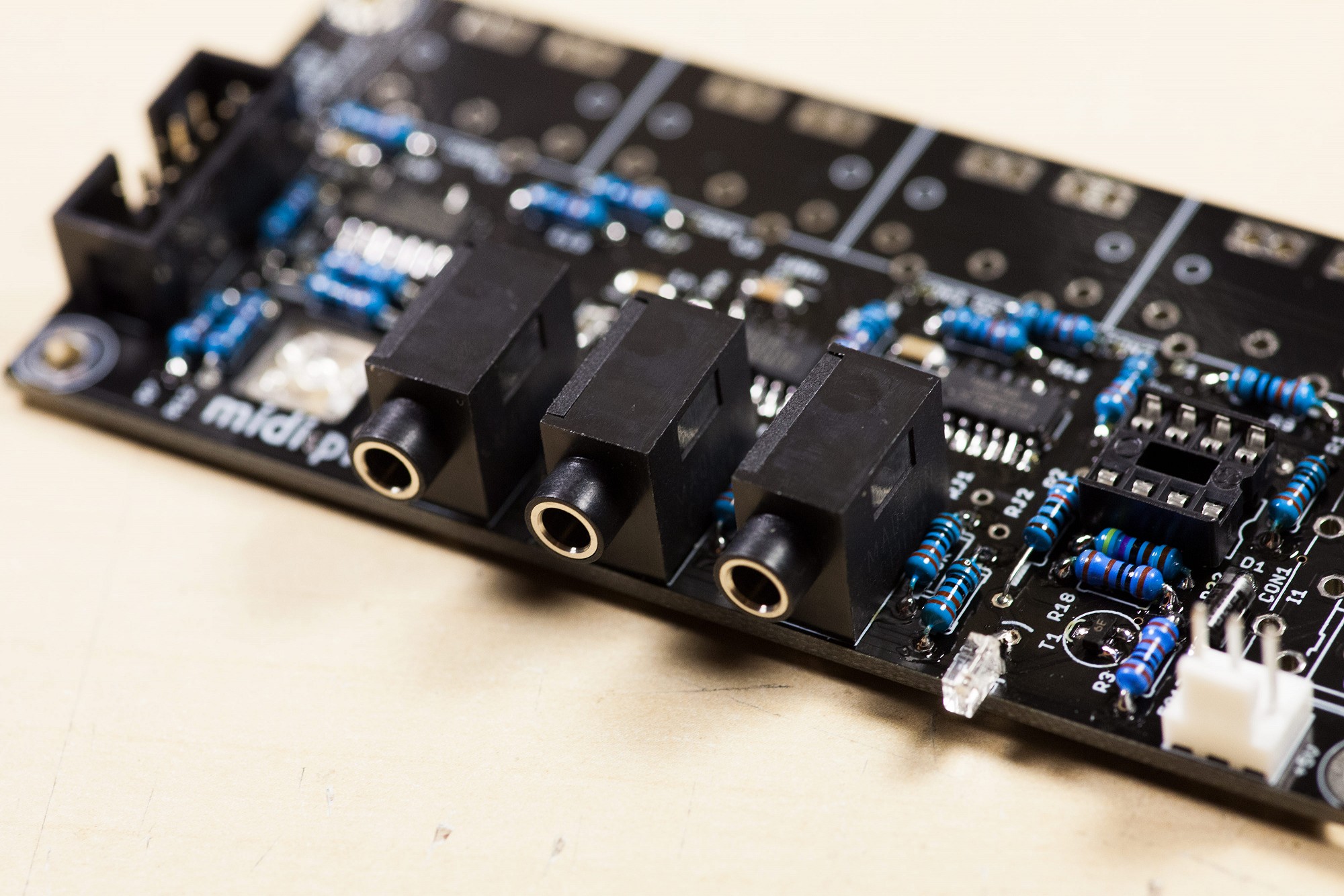
Install the 3.5mm jacks in JACK1-JACK3.
Install the 3.5mm jacks in JACK1-JACK3.
Step 23
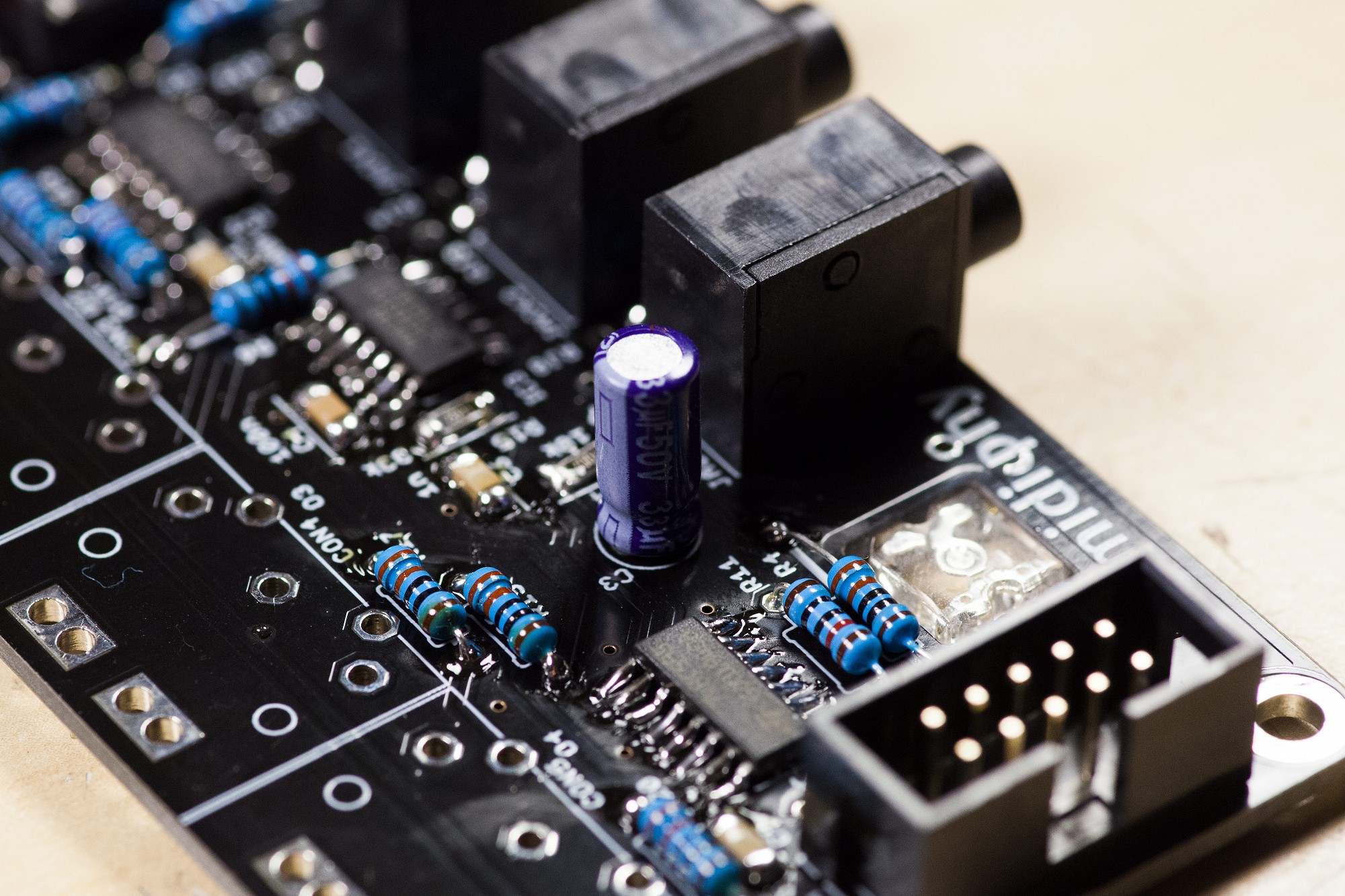
Install the polarized 33uF cap at C3.
Ensure that the side marked with (-) is aligned as shown.
The longer pin on the other side of the cap goes into the (+) pad (marked on the silkscreen).
Install the polarized 33uF cap at C3.
Ensure that the side marked with (-) is aligned as shown.
The longer pin on the other side of the cap goes into the (+) pad (marked on the silkscreen).
Step 24
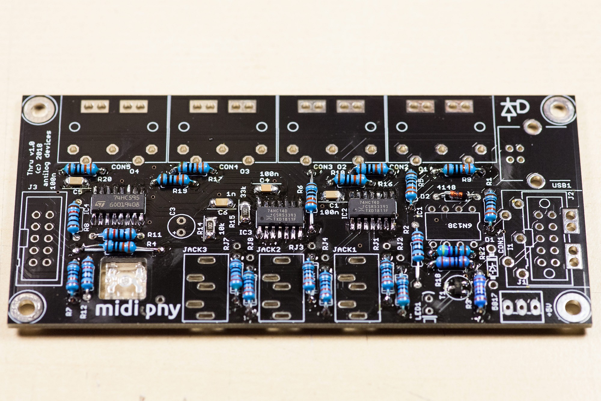
Install the 5-pin DIN sockets in CON1-CON5 (see note).
It is recommended to "tack" one pin of each first, then to check that all sockets are properly aligned. If they are misaligned or sitting off the board, reflow the necessary pad(s) before continuing on with the remaining pins.
Note: install a shrouded 2x5 IDC header for J2 and omit CON1 for additional chained boards.
Step 25
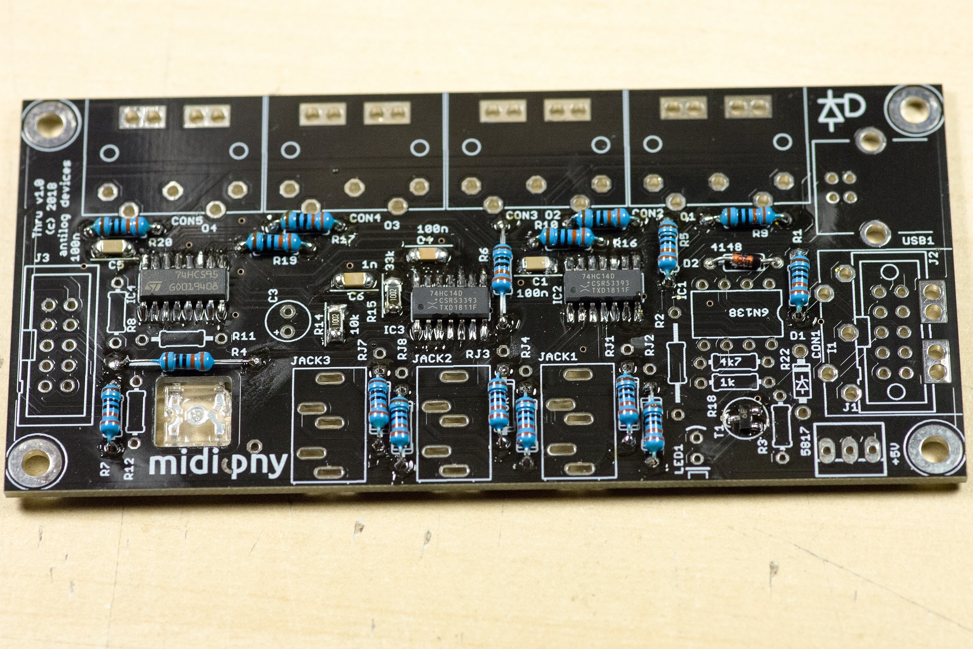
To finalize the build, install the 6N138 optocoupler as shown - align the marked side with the notch on the IC socket. It is likely you'll need to straighten the pins by carefully bending them back towards the IC body.
To finalize the build, install the 6N138 optocoupler as shown - align the marked side with the notch on the IC socket. It is likely you'll need to straighten the pins by carefully bending them back towards the IC body.