


product details
Transmute8 PCB (Eurorack)
Product ID: P-EUR-04
The main board for the analog expander. Processes and scales incoming CV from the DAC and distributes it to the panel PCB.
Weight: 20 grams
in stock
21.98 €
incl. VAT, excl. shipping
Bill of Materials / Placement Guide
Label
Package
Name
Side
Part Link
Notes
Required Mouser parts
Can be directly transferred into your
mouser cart by copying & pasting the text below into the mouser part list import tool (you
may need to log in at mouser before the tool is available):
https://www.mouser.com/tools/part-list-import.aspx
https://www.mouser.com/tools/part-list-import.aspx
603-RT1206FRE0749K9L|40
80-C1206C104M5R|11
667-EEU-EB1J100SH|2
77-VJ1206A100JXQCBC|16
511-TL074IYDT|4
517-929836-01-36-RK|1
517-974-01-04-RK|1
517-929974-01-08-RK|1
517-929974-01-11-RK|1
623-2743001112LF|2
652-CR1206-JW-102ELF|1
652-CR1206JW-134ELF|8
652-CR1206JW-104ELF|8
652-CR1206JW-221ELF|8
81-PV36W503C01B00|8
595-LM4040A50IDBZR|1
The BOM checker 'bot says:
All parts referenced from the CAD master files have been validated. The BOM should be safe to order!*
* Disclaimer: although we have taken the best care possible, we cannot guarantee 100%
accuracy and we cannot be held liable for erroneous orders when using
this tool, including (but not limited to) incorrect quantities and/or
types of components ordered through midiphy or other suppliers.
Recommended products
These additional products may be of interest:
A1 Frontpanel (Eurorack)
C-EUR-05
The A1 - Analog Expander module frontpanel by Hallik Engineering. Natural aluminium, with black silkscreen labels. 6HP.
21.98 €
incl. VAT, excl. shipping
Octal PCB (Eurorack)
P-EUR-02
Front panel PCB with 3.5mm sockets and LED indicators. Works with both digital and analog expanders.
17.98 €
incl. VAT, excl. shipping
SuperDAC PCB (Eurorack)
P-EUR-05
Quality DAC PCB for the analog expander using MAX5500 SSOPs and separate voltage references.
15.98 €
incl. VAT, excl. shipping
SEQ v4+ Eurorack Modules Essential Kit
K-EUR-01
A set of Eurorack PCBs, frontpanels and essential parts at a discount! Rack usage: up to 22HP, case depth 50mm. Needs further parts to be completed. Does not include required SEQ v4+/v4.
259.98 €
incl. VAT, excl. shipping
Tech Notes
Using a digital multimeter, match the resistance values of resistor groups 1RXX, 2RXX, 3RXX etc. - the exact value is unimportant. No need to match the values between groups 1RXX-8RXX.
Resistors 1R34, 2R35...8R41 add an offset for the respective channel. Thus it is possible to configure unipolar output channels by omitting these. You could create a board with e.g. half bipolar, half unipolar output channels. Considering the tuning range of typical VCOs, bipolar CVs make the most sense. But there might be applications where unipolar voltage output (0V ~ 10V) is helpful.
Caution: if you are using unipolar output, the corresponding LED resistors on the octal PCB should be changed to suit the higher voltage range; here we'd recommend 2k2 resistors for R1-R8 on the octal PCB.
Tip: you could use a different LED color on octal to indicate the unipolar channels.
Left image: Scaling circuit for the transmute8 board. The incoming CV is scaled with the first op amp and linear V/oct tuning is adjusted with VR1-8. The second op amp re-inverts the signal and adds an offset (optional). It is best if the summing and feedback resistors are closely matched to mitigate errors.
Both inverting amplifiers have simple filters. The 10p capacitor values could be optimized further. The final output is a compensated protection circuit typically seen in Eurorack modules.
The circuits are repeated with sequential component numbering for channels 3-8.
Both inverting amplifiers have simple filters. The 10p capacitor values could be optimized further. The final output is a compensated protection circuit typically seen in Eurorack modules.
The circuits are repeated with sequential component numbering for channels 3-8.
To calibrate, use a digital multimeter to measure the output in volts of the respective CV output port.
Within the SEQ v4+, first check, that you are using "AOUT" as a hardware protocol (rightmost encoder on the right screen in the CV Options menu). Also in the CV Options menu, choose CV1 (leftmost encoder on the left screen) and use the second encoder from the right (still on the left screen) to choose a calibration voltage of 5V, which would correspond to a C3 note, as the Transmute8 has an output offset of -5V. Here, we would aim for a reading of 0.000V on the multimeter.
Now use the hardware trimpot on the Transmute8 of this channel to adjust to get a readout close to 0.000V on the multimeter.
Now you can use the rightmost encoder on the left v4+ screen to fine-tune adjustment offsets (linear software interpolation!) for every volt in the range -4V to +5V (display-voltage 1V - 10V because of the -5V offset).
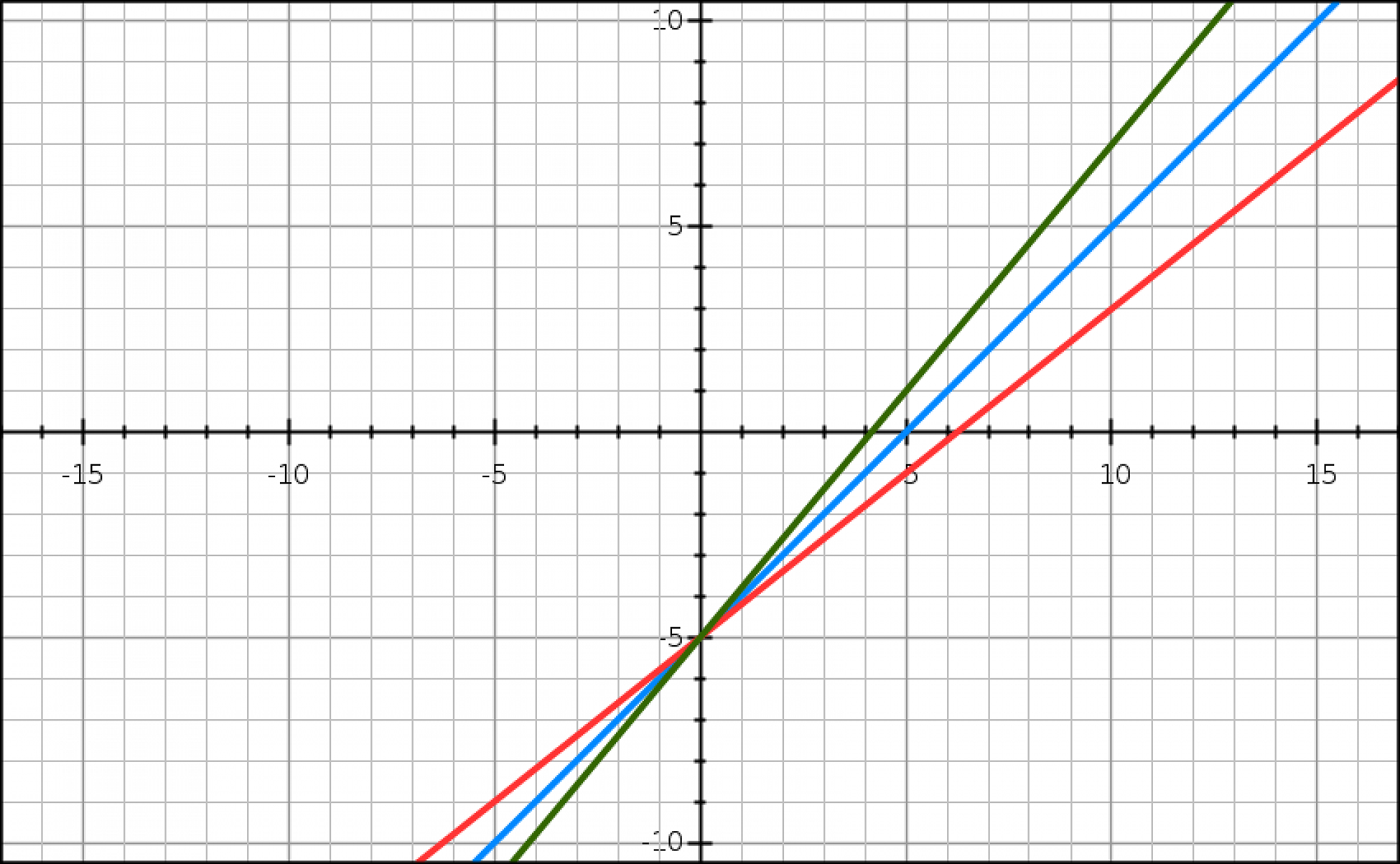
As the trimpot calibrates the slope of the amplification, not much tuning is possible at the -5V output voltage point. In the left diagram we are aiming to reach the blue line. Every other voltage step other than -5V can be fine tuned to quite precisely match a full volt. Most important are the voltages between -2V to 2V, as these span the "five center octaves" around C3 (0V output). Thus the SEQ v4+ allows to span an "interpolation net" of 9 voltage offsets, that allow to adjust any linearity issues of the DAC. Normally not much adjustment should be needed (offsets in the range -20 to +20).
You could also watch the calibration chapter in the DIY midiphy SEQ V4+ Eurorack Expansion Modules build tutorial video.
Within the SEQ v4+, first check, that you are using "AOUT" as a hardware protocol (rightmost encoder on the right screen in the CV Options menu). Also in the CV Options menu, choose CV1 (leftmost encoder on the left screen) and use the second encoder from the right (still on the left screen) to choose a calibration voltage of 5V, which would correspond to a C3 note, as the Transmute8 has an output offset of -5V. Here, we would aim for a reading of 0.000V on the multimeter.
Now use the hardware trimpot on the Transmute8 of this channel to adjust to get a readout close to 0.000V on the multimeter.
Now you can use the rightmost encoder on the left v4+ screen to fine-tune adjustment offsets (linear software interpolation!) for every volt in the range -4V to +5V (display-voltage 1V - 10V because of the -5V offset).
As the trimpot calibrates the slope of the amplification, not much tuning is possible at the -5V output voltage point. In the left diagram we are aiming to reach the blue line. Every other voltage step other than -5V can be fine tuned to quite precisely match a full volt. Most important are the voltages between -2V to 2V, as these span the "five center octaves" around C3 (0V output). Thus the SEQ v4+ allows to span an "interpolation net" of 9 voltage offsets, that allow to adjust any linearity issues of the DAC. Normally not much adjustment should be needed (offsets in the range -20 to +20).
You could also watch the calibration chapter in the DIY midiphy SEQ V4+ Eurorack Expansion Modules build tutorial video.