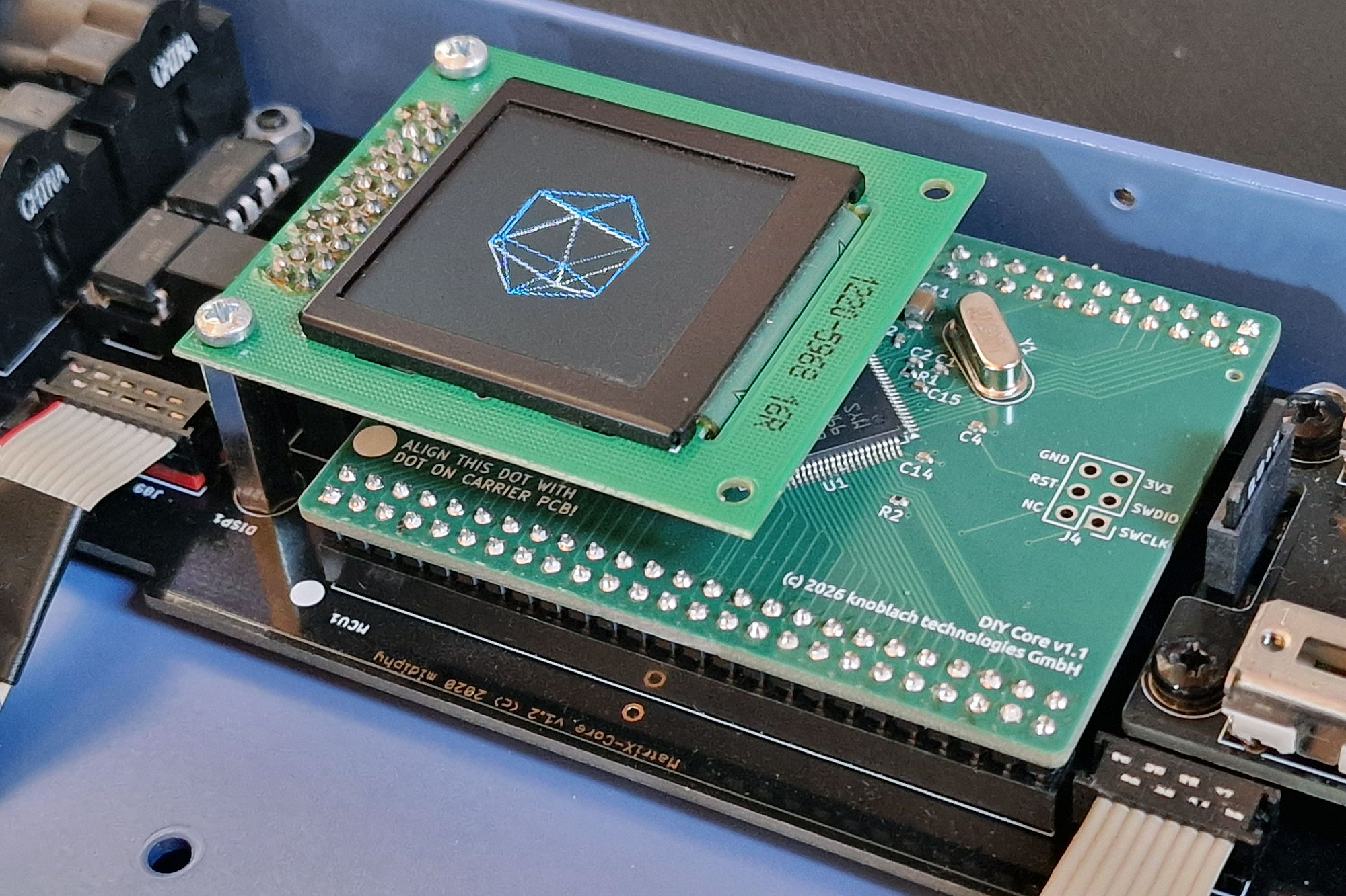


product details
MCU DIYCore (407VGT), 1MB flash, bootloader
Product ID: M-407-03
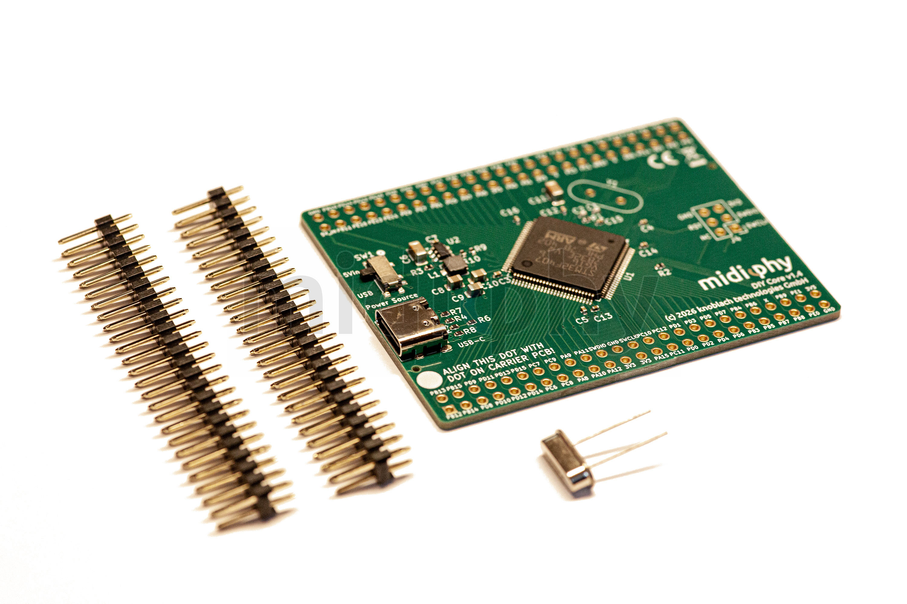
STM32F407VGT core with MIDIbox bootloader, 1MB flash memory. Compatible with MBSEQ v4+, midiphy MatriX and midiphy LoopA v2. Includes two 2x25 pin headers and 8MHz crystal.
Weight: 20 grams
Directly upload firmware using MIOS Studio via a USB-C cable; no ST-Link required, installation: see tutorial below!
in stock
29.99 € New!
incl. VAT, excl. shipping · Your legal guarantee rights
Recommended products
These additional products may be of interest:
Free Shipping!
midiphy MatriX (with pro metal case) Essential Kit
K-MTX-01
midiphy MatriX Essential Kit with pro metal case. Further parts and a 12V/5A PSU are required (see BOM and PSU note).
1,189.99 €
incl. VAT, excl. shipping
LoopA 2024 Enhanced Metal Case Essential Kit
K-LPA-02
Enhanced 2024 facelift LoopA essential kit, also including the OLED, light|shields, custom superQ keycaps and the metal case from Hallik Engineering.
449.99 €
incl. VAT, excl. shipping
SEQ v4+ Enhanced LH Essential Kit
K-SFE-01L
MIDIbox SEQ v4+ enhanced edition kit. LH case incl. rack kit (optional, needs 3U and 3mm of rack height), PCBs, UI parts, light|shields and L4 caps. Needs further parts to be completed.
929.99 €
incl. VAT, excl. shipping
SEQ v4+ Enhanced RH Essential Kit
K-SFE-01R
MIDIbox SEQ v4+ enhanced edition kit. RH case incl. rack kit (optional, needs 3U and 3mm of rack height), PCBs, UI parts, light|shields and L4 caps. Needs further parts to be completed.
929.99 €
incl. VAT, excl. shipping
DIYCore Assembly Photo Tutorial
Step 1
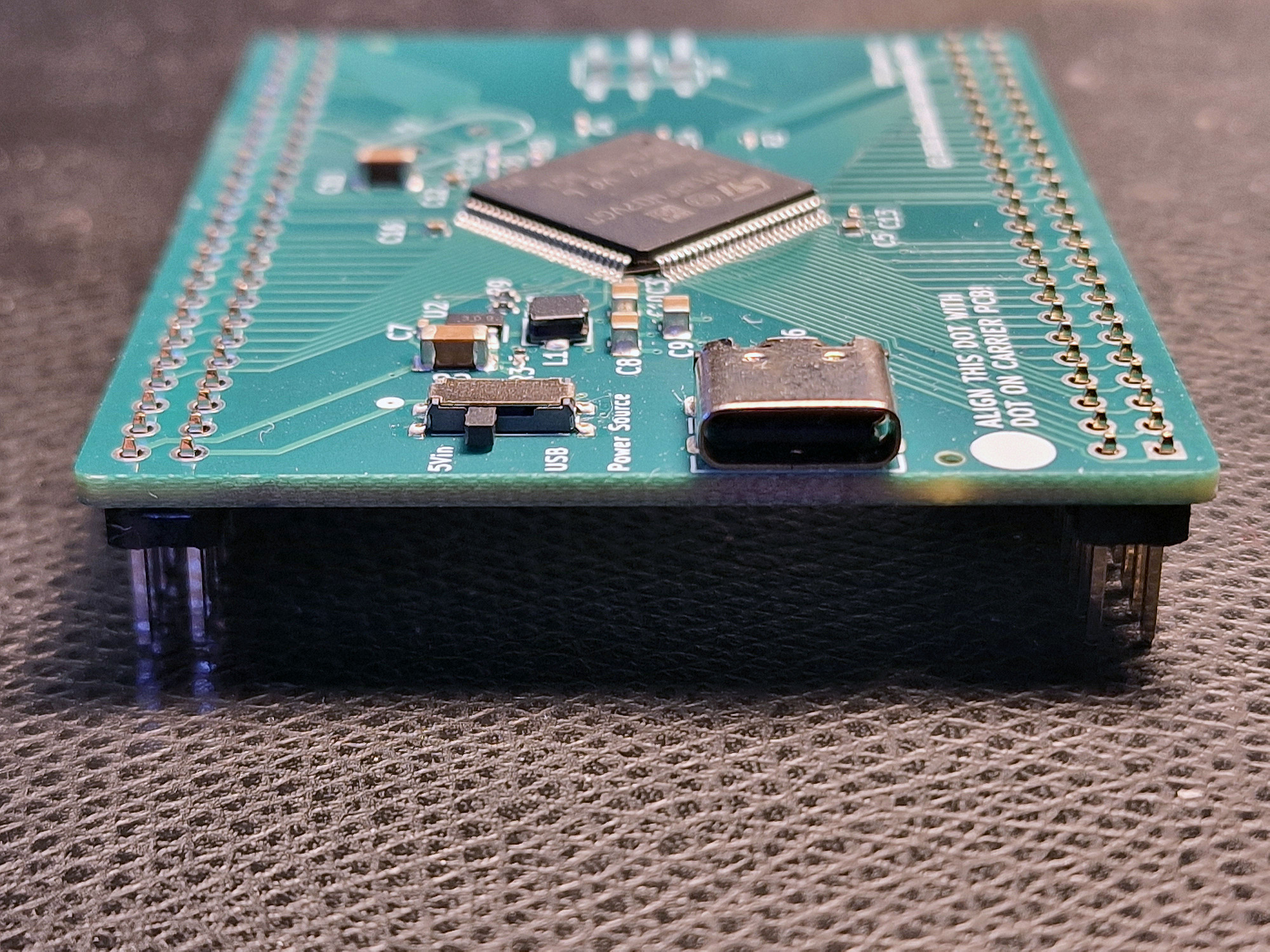
Insert the 2x25 pin headers as shown - and place the core upright - make sure the pin headers are truly vertical (see picture), then solder them from the top.
Insert the 2x25 pin headers as shown - and place the core upright - make sure the pin headers are truly vertical (see picture), then solder them from the top.
Step 2
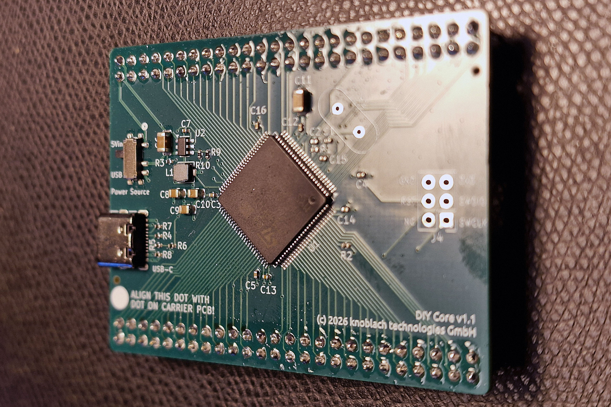
This is how it should look. Check for proper solder connections and no unwanted solder bridges.
This is how it should look. Check for proper solder connections and no unwanted solder bridges.
Step 3
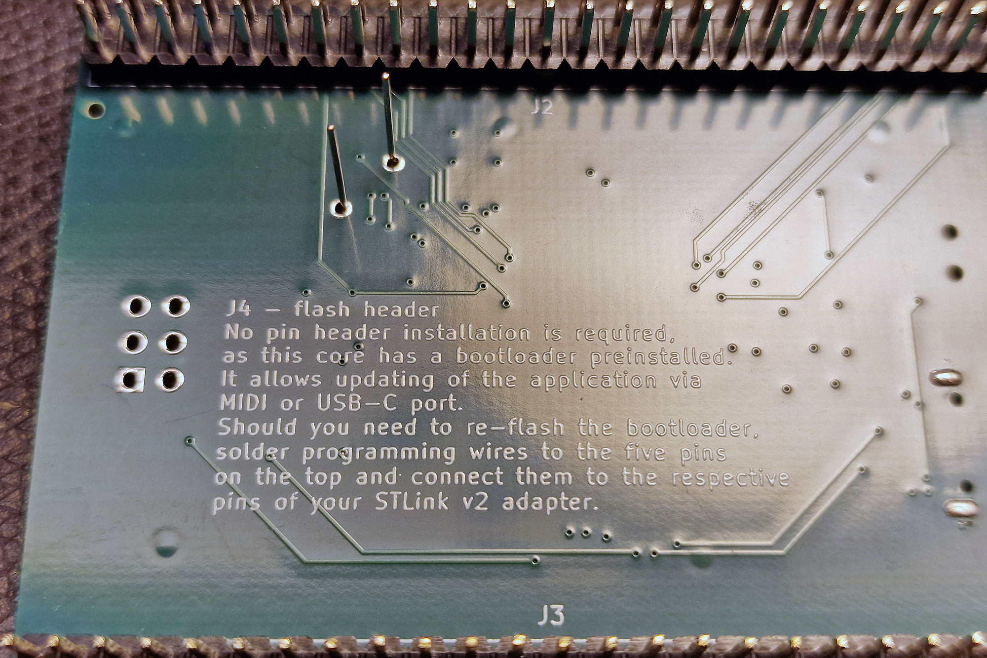
Insert the 8MHz crystal from the top side (polarity does not matter) and turn over the DIYCore. You should see the two pins protruding from below like in the photo. Cut them with your wire cutter (careful to protect your eyes, possibly low-flying pieces of metal!) and solder them.
Insert the 8MHz crystal from the top side (polarity does not matter) and turn over the DIYCore. You should see the two pins protruding from below like in the photo. Cut them with your wire cutter (careful to protect your eyes, possibly low-flying pieces of metal!) and solder them.
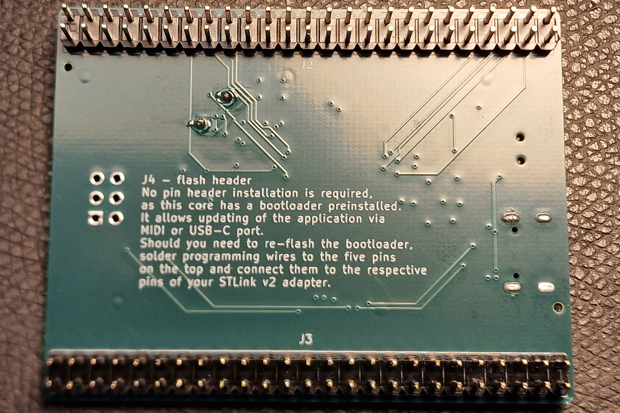
Step 4
This is how it should look. Congratulations, your DIYCore is completed!
This is how it should look. Congratulations, your DIYCore is completed!
Step 5
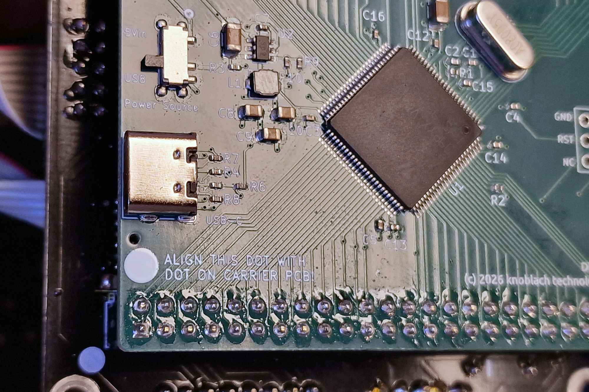
When installing in SEQ v4+, MatriX or LoopA v2 core boards: make sure to align the white dot on the DIYCore PCB with the white dot on the carrier PCB. Make also sure the Power Source switch is set to "5V" (then the DIYCore obtains power from the carrier PCB, not from the USB port). Enjoy! :)
When installing in SEQ v4+, MatriX or LoopA v2 core boards: make sure to align the white dot on the DIYCore PCB with the white dot on the carrier PCB. Make also sure the Power Source switch is set to "5V" (then the DIYCore obtains power from the carrier PCB, not from the USB port). Enjoy! :)