nexusMIDI // learn: manual and tutorials
Manual
Follow the quickstart manual to correctly install your nexusMIDI, set up phybus cabling, and splice your first virtual patch.
Follow the quickstart manual to correctly install your nexusMIDI, set up phybus cabling, and splice your first virtual patch.
Download quick start manual
nexusMIDI quick start manual v1 (5.12M)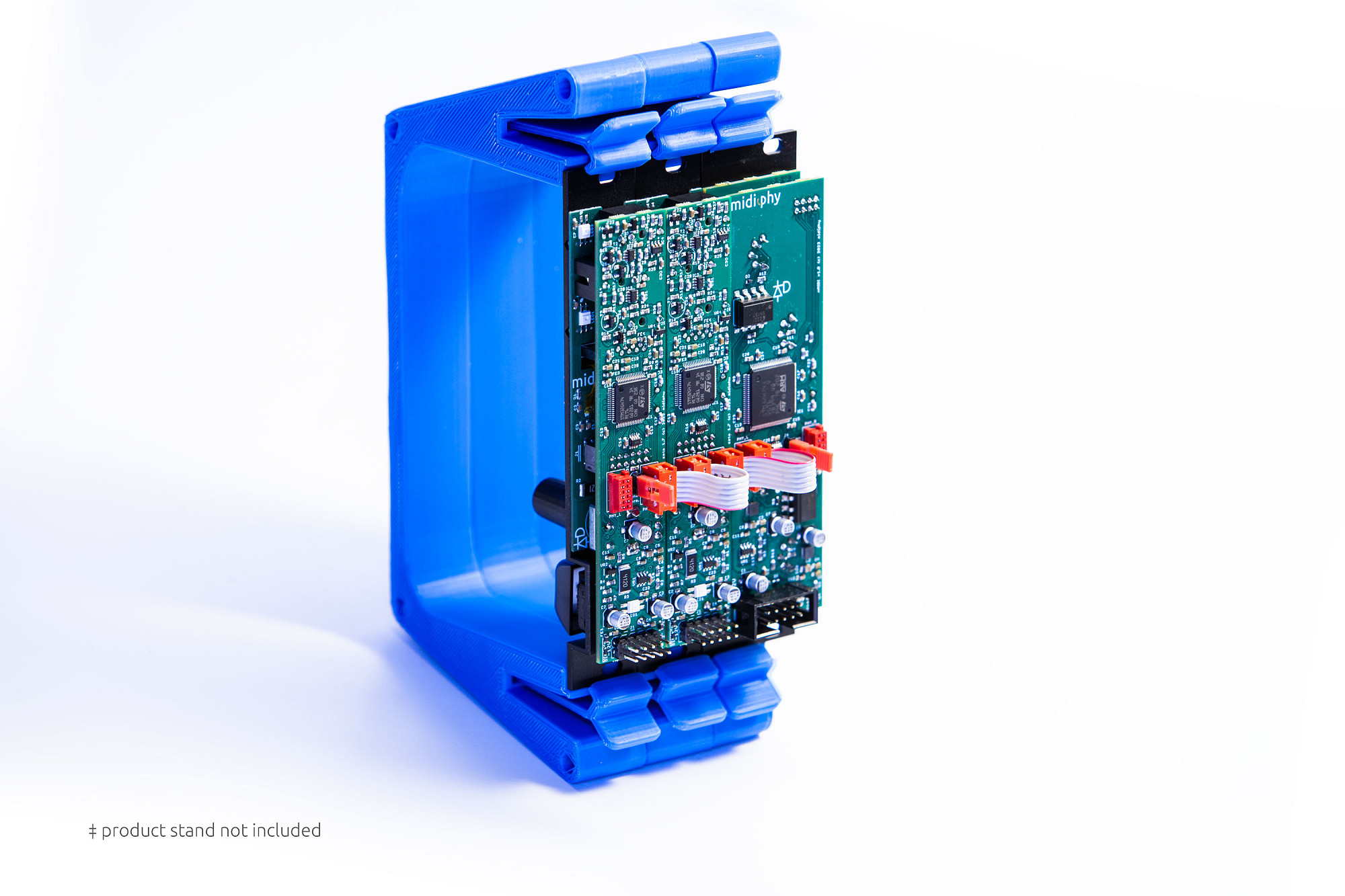
Quick start
1. Connect phybus cables between nexusMIDI and your zetaSID modules using the contained phybus ribbon cables (PHY_L to PHY_R)
2. Place termination jumpers on the two outer modules of your phybus chain (the "end term." headers)
3. Connect eurorack power using the standard 10-pin IDC cable (red stripe to –12V) and fasten the modules in your rack
4. Power up your eurorack system
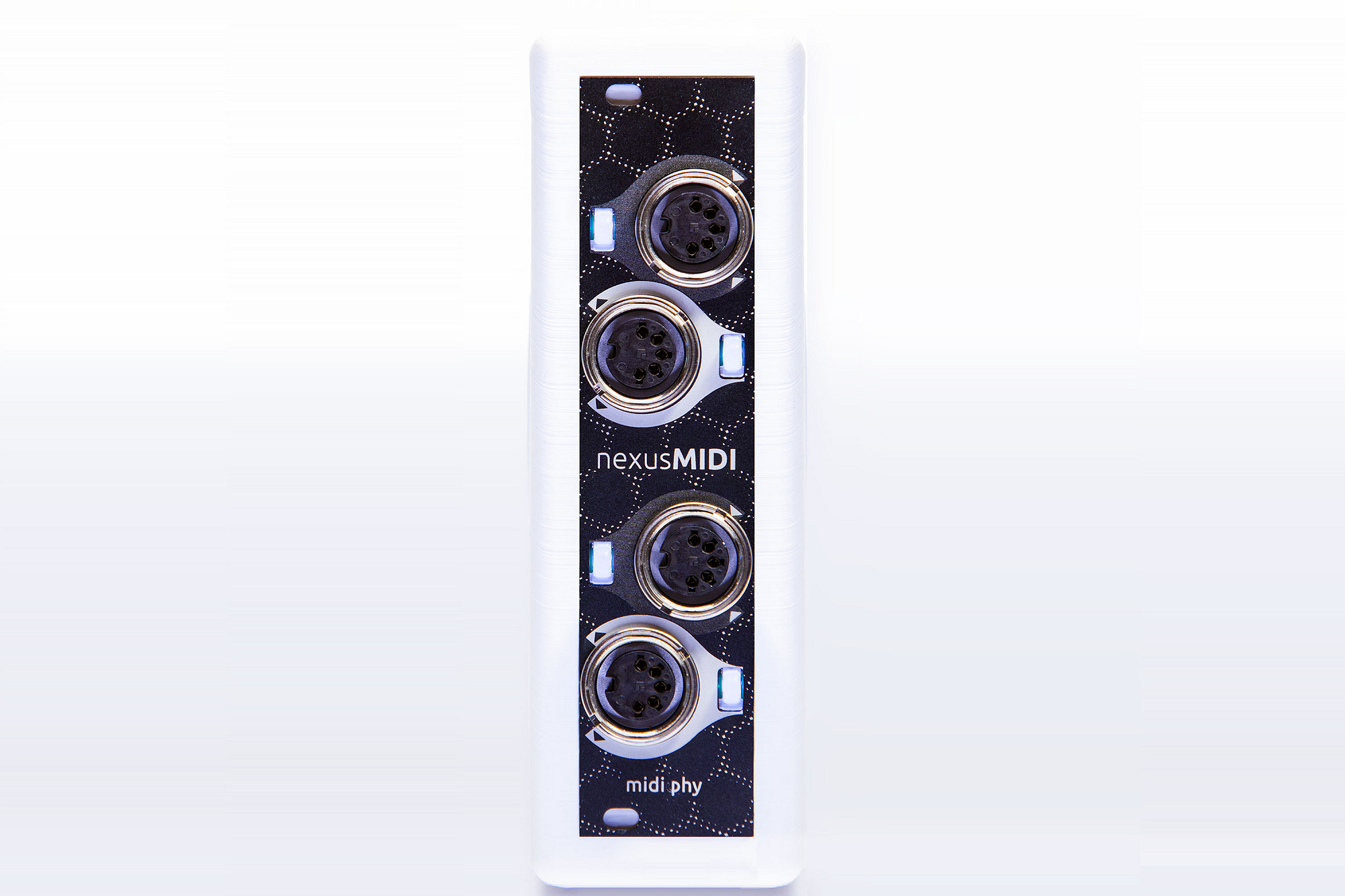
5. Connect your MIDI gear: plug a MIDI keyboard or controller into one of the MIDI IN ports
6. Splice the MIDI input: press the LEDome button next to the MIDI IN port on nexusMIDI. All connected modules will show the splice screen.
7. Assign to zetaSID: on your zetaSID, turn the encoder to select "MIDI In 1" or "MIDI In 2" and press the key to confirm
8. Play: your MIDI keyboard now controls zetaSID!
If required, you can change input parameters (e.g. the MIDI channel) on the zetaSID MIDI input socket screens.
For polyphonic playback, configure additional zetaSIDs as "Agents" with the same instrument ID as your "Chief" - and splice them to your nexusMIDI input port.
1. Connect phybus cables between nexusMIDI and your zetaSID modules using the contained phybus ribbon cables (PHY_L to PHY_R)
2. Place termination jumpers on the two outer modules of your phybus chain (the "end term." headers)
3. Connect eurorack power using the standard 10-pin IDC cable (red stripe to –12V) and fasten the modules in your rack
4. Power up your eurorack system
5. Connect your MIDI gear: plug a MIDI keyboard or controller into one of the MIDI IN ports
6. Splice the MIDI input: press the LEDome button next to the MIDI IN port on nexusMIDI. All connected modules will show the splice screen.
7. Assign to zetaSID: on your zetaSID, turn the encoder to select "MIDI In 1" or "MIDI In 2" and press the key to confirm
8. Play: your MIDI keyboard now controls zetaSID!
If required, you can change input parameters (e.g. the MIDI channel) on the zetaSID MIDI input socket screens.
For polyphonic playback, configure additional zetaSIDs as "Agents" with the same instrument ID as your "Chief" - and splice them to your nexusMIDI input port.
phybus connections
The midiphy phybus system is a high-speed, expandable data protocol for low-latency routing of data streams, MIDI, and CV/gate signals. Additionally, connected modules can share user interface elements and virtual services among each other.
Connection guidelines:
Daisy-chain adjacent modules using phybus ribbon cables from PHY_R to PHY_L
Consider making all phybus connections before connecting power and mounting modules
Leave the outer PHY_L and PHY_R connectors empty
Place exactly two termination jumpers: one on each of the two outer modules
Do not place termination jumpers on internal modules
When adding modules, remove all jumpers except those on the two end modules
Do not use the phybus headers for any other purpose
Maximum phybus network size: 16 modules
Maximum total phybus cable length: 150 centimeters
Power connection
Standard 10-pin eurorack header with –12V indicated by the red stripe
The module is protected from reverse polarity, but make all connections with rack power switched off
5V bus power is not required
MIDI routing and splicing
A virtual connection between a physical MIDI port and any module on the phybus network is established by creating a splice between them.
To splice a MIDI input:
Press the LEDome button next to a MIDI IN port on nexusMIDI
All OLEDs on the phybus network display the splice screen
On the target module (e.g. zetaSID), turn the encoder to select a compatible input socket (MIDI In 1 or MIDI In 2)
Press the key to confirm the connection
MIDI input socket options on zetaSID:
MIDI channel: Omni or 1–16
Velocity: On (scales output DCA) or Off (full velocity)
Clock: Auto, Agent, or Chief mode
To splice a MIDI output:
Press the LEDome button next to a MIDI OUT port on nexusMIDI
On the source module, select the MIDI Out socket
Press the key to confirm
MIDI output options on zetaSID:
MIDI channel: 1–16
Send ARP: forward arpeggio notes to MIDI output
LEDome color meanings:
Warm white: port available, flashes with (unused) activity
Cool white: splice process started
Off: port spliced and idle
Violet: MIDI data received
Pink: MIDI data transmitted