


Building the midiphy MatriX (Photo Tutorial) v1.02
Welcome!
This is a step-by-step photo tutorial with in-depth descriptions that explain how to build your new midiphy MatriX.
Always check the and ensure that you have soldered every required part of each PCB.
Enjoy building and using your new ! :)
Keycaps
While this build document contains pictures of the L4-style keycaps, the release MatriX uses the newer superQ keycaps - the build process is identical.
Safety Notice
Make sure to follow this tutorial step by step.
I.e. make sure to first solder in the Matias switches before testing the ePixel LED chain - this will add sufficient light dampening to the LEDs.
Required Tools
For building the MatriX, you'll need a normal temperature-controlled soldering station with a standard tip (e.g. 1.6mm), normal solder (e.g. 0.7mm), a flux pen (recommended), high-quality desoldering braid, a loupe or magnifying glass and SMT pincers for aligning the parts on the PCBs.
For creating the cables, a crimp tool to create Molex connectors and a mechanical mini table/bench vise is recommended, but these are very affordable. Normal flat nose pliers and a side cutter for cutting THT pins are also required.
When building the prototype MatriCes, installing the nearly ~300 ePixel LEDs, we've often encountered ePixel LEDs, that need replacement - here, a SMT hot air rework station (very affordable, starting at 30€) is highly recommended, as you can evenly heat up all four LED pins and extract the LED with your SMT pincers within seconds. Don't worry, if you will need to replace a few LEDs - we've packed a few spare ePixels in your essential kit!
All PCBs were designed for hand-soldering, all parts are large-size SMT 1206 components with most pads bigger than their THT counterparts. Soldering them, in our opinion, is easier and quicker than soldering THT parts, especially when you're soldering ~300 LEDs - no need to snip off their legs! :)
Chapter 1: MatriX Core PCB
1.1 Let's start...
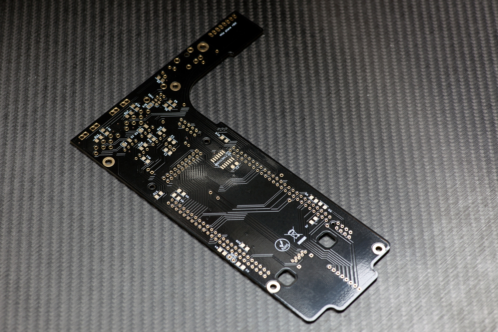
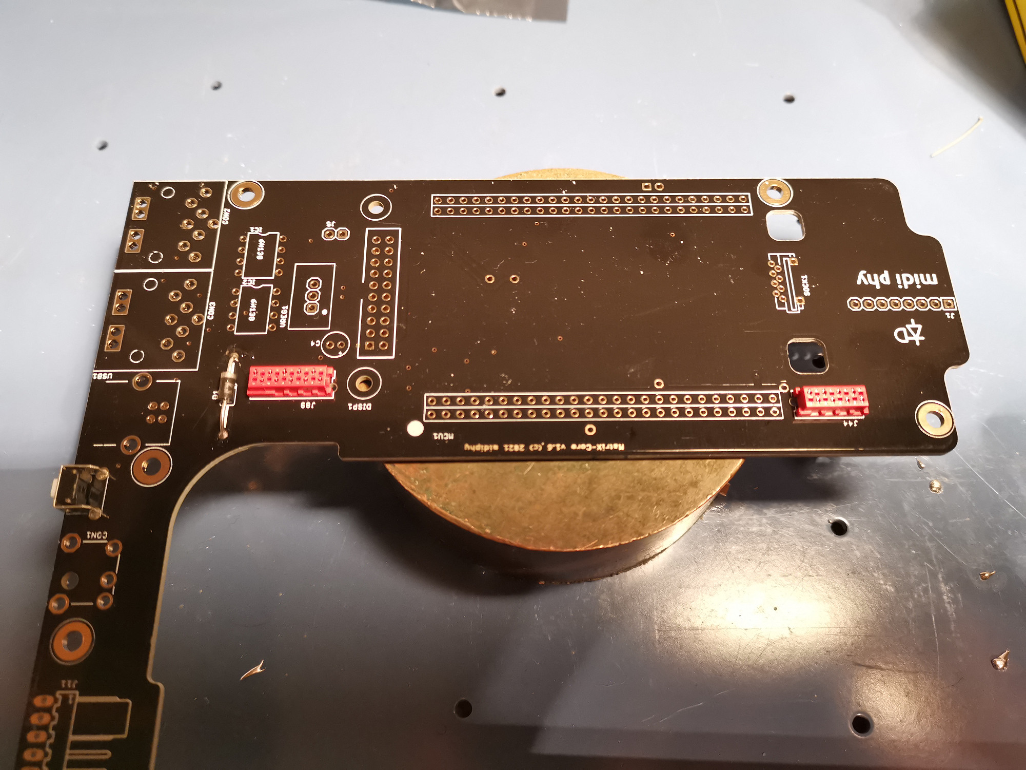
...with the MatriX Core PCB! :)
Turn it over to solder the backside parts; these are all large SMT 1206 parts. These are easy to handle and quicker to solder than their THT counterparts.
To easily solder ICs and multi-pin SMT parts, you could use a flux pen and employ a drag-soldering method like shown for example in the midiphy LoopA assembly video tutorial:
1.2 TVS Diode
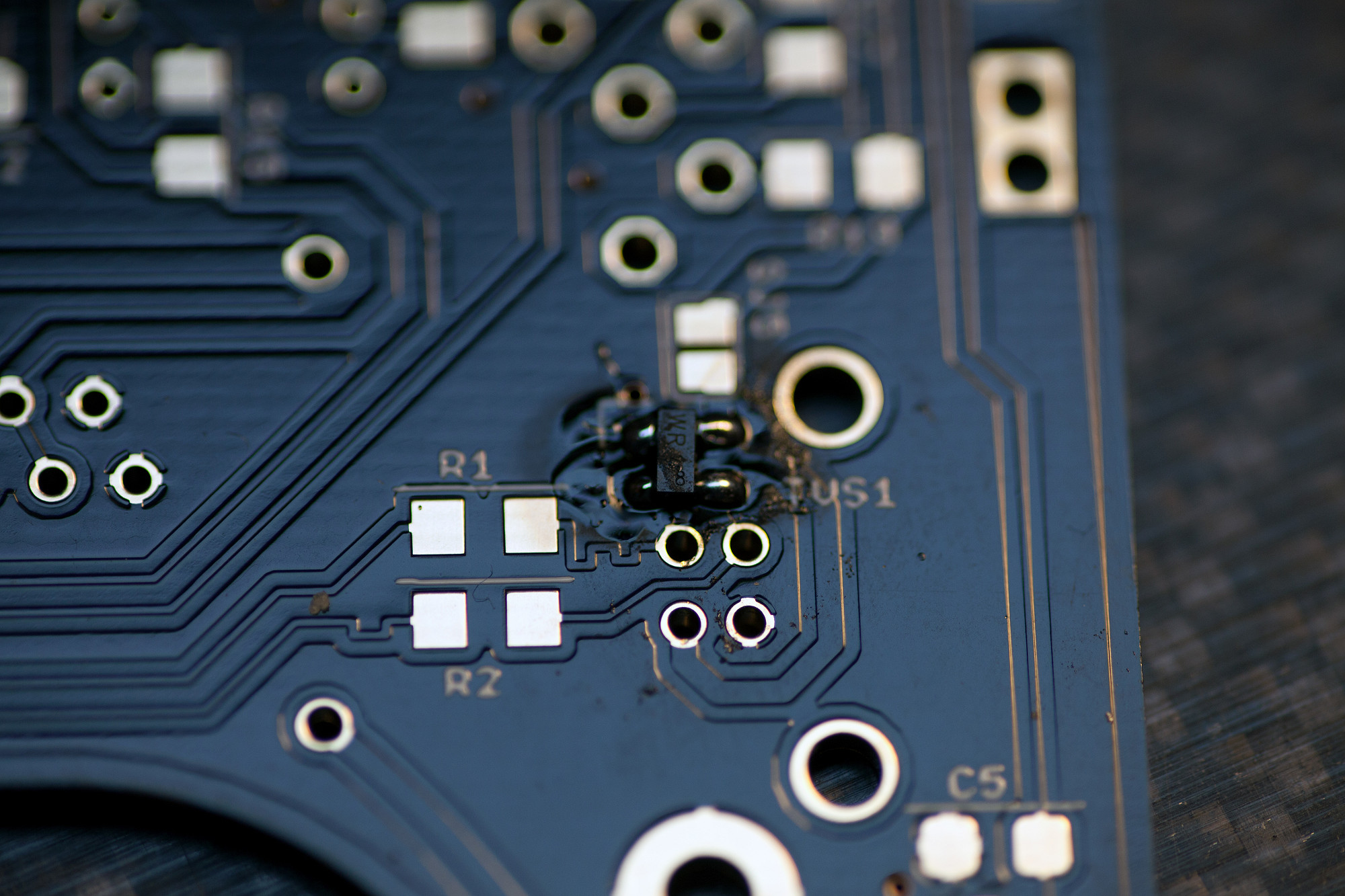
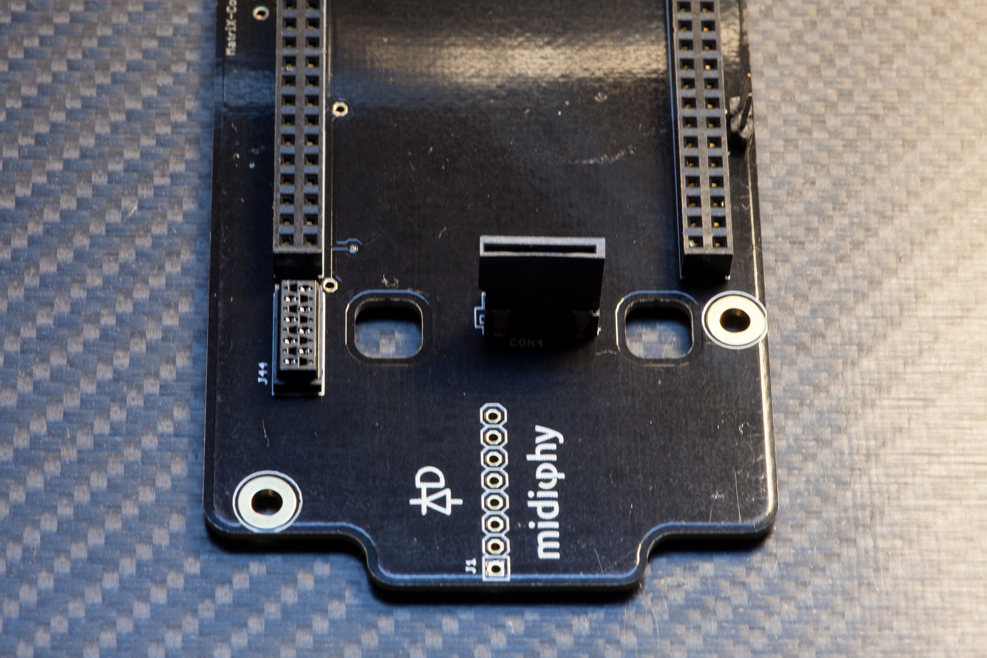
Solder TVS1 observing polarity.
This small USB protection diode is asymmetric and has one larger pin. Align it to the larger pad (marked with silkscreen) and solder one pin first. Make sure all other pins are correctly aligned with the other pads and then solder the remaining pins.
Solder TVS1 observing polarity.
This small USB protection diode is asymmetric and has one larger pin. Align it to the larger pad (marked with silkscreen) and solder one pin first. Make sure all other pins are correctly aligned with the other pads and then solder the remaining pins.
1.3 74HCT125
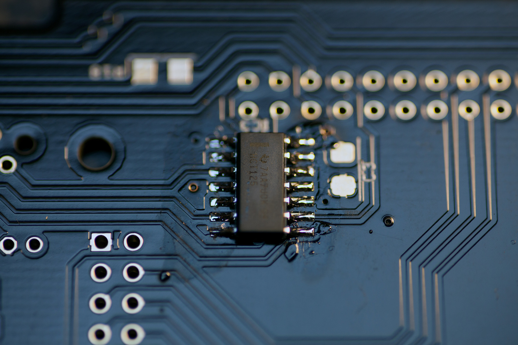
Solder IC3 observing polarity.
Make sure you align the marking on the pin with the notch on the silkscreen. An easy method to solder the IC is to solder two legs on one side first, then apply your flux pen and solder first on the other side and then on the side you "tacked". Here's an in-depth description of the technique:
After soldering, check all pins with a loupe/magnifying glass for unwanted bridges and for proper contact to the PCB, also check from the sides, as there might be unwanted "lift" and a pin might not have reached a pad on the PCB. The above tutorial video link explains how to fix errors with desoldering braid, too.
1.4 SMT Capacitors
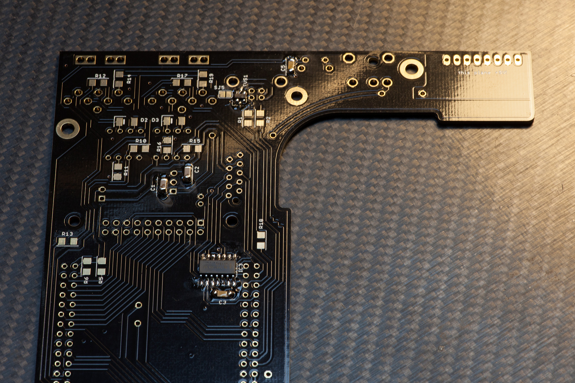
Solder C3, C5: these parts have no polarity
These common SMT parts are easily soldered by tinning one pad first and then using your SMT pincers to push the SMT part on, while heating that pad. Afterwards solder the other pad. You might want to reflow the first pad you used for pushing on the part with a tiny bit of solder (or flux), if the solder point is not shiny :).
1.5 SMT DIODES
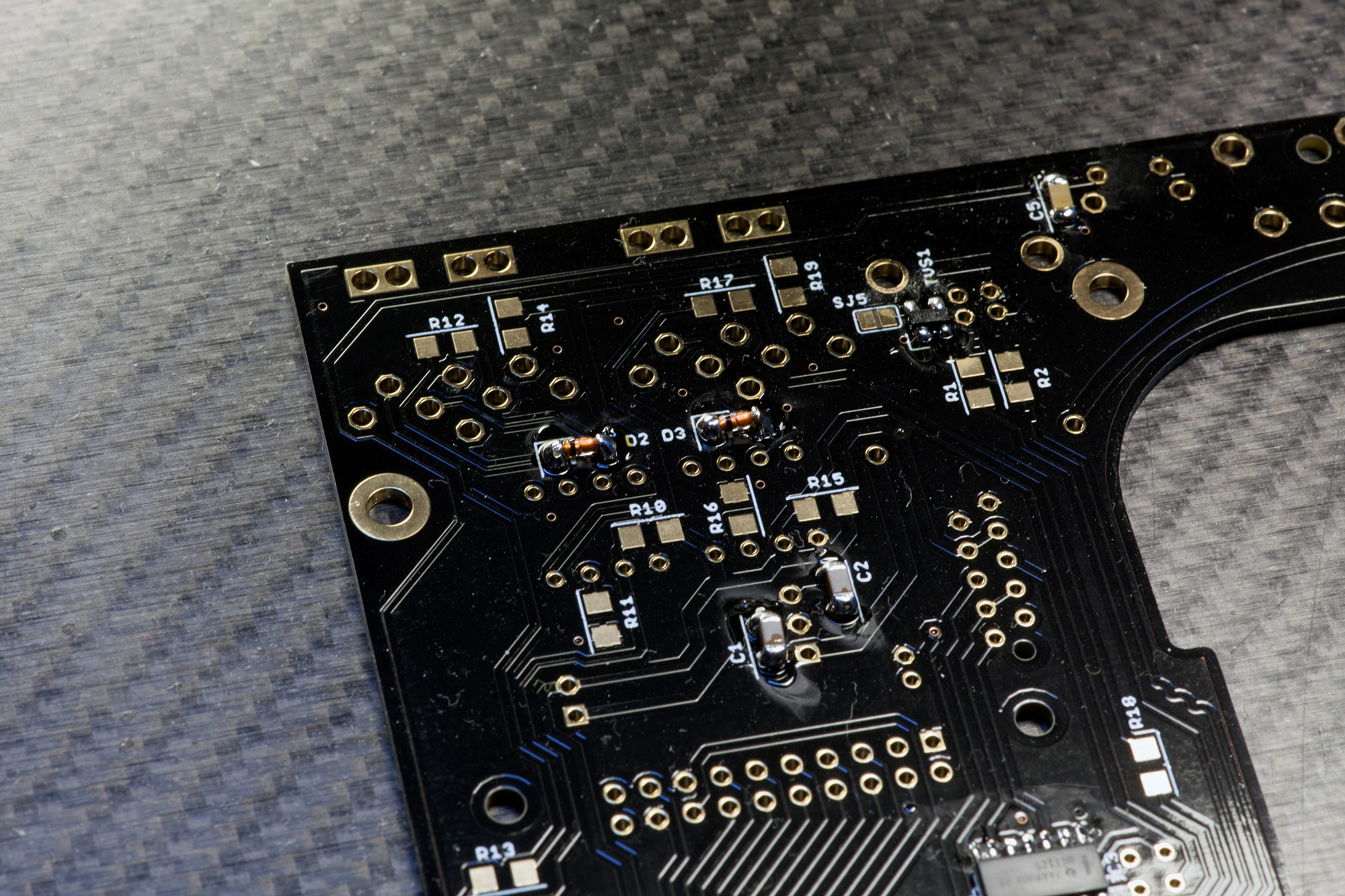
Solder D2 and D3 observing polarity.
These are polarized parts, make sure you align the marking on the diode with the marking on the PCB.
Solder D2 and D3 observing polarity.
These are polarized parts, make sure you align the marking on the diode with the marking on the PCB.
1.6 SMT RESISTORS
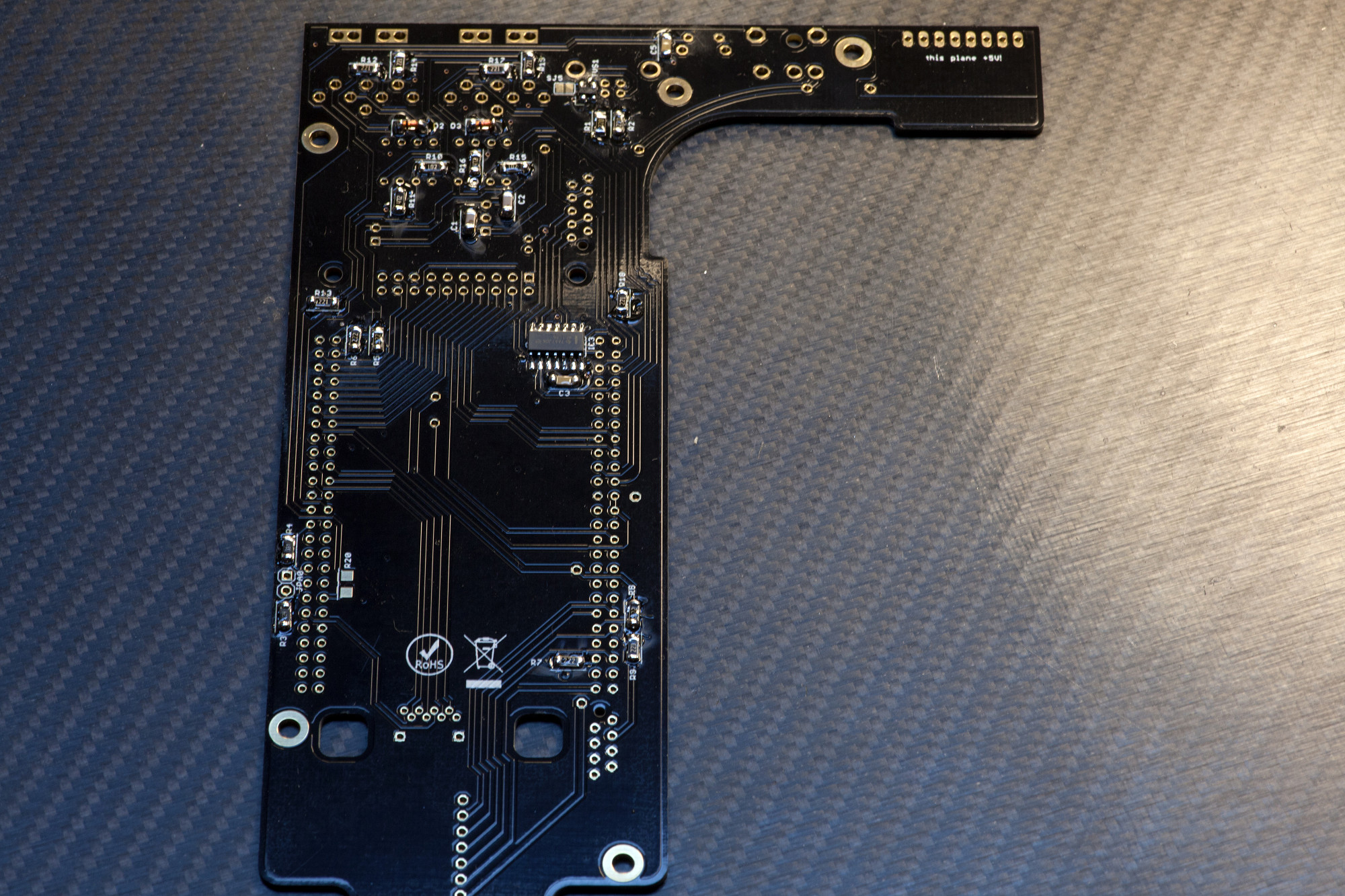
Solder R1-R20 observing their different values.
These are not polarized, but make sure you install the correct values in the correct positions - always refer to the BOM.
Solder R1-R20 observing their different values.
These are not polarized, but make sure you install the correct values in the correct positions - always refer to the BOM.
1.7 THT DIODE
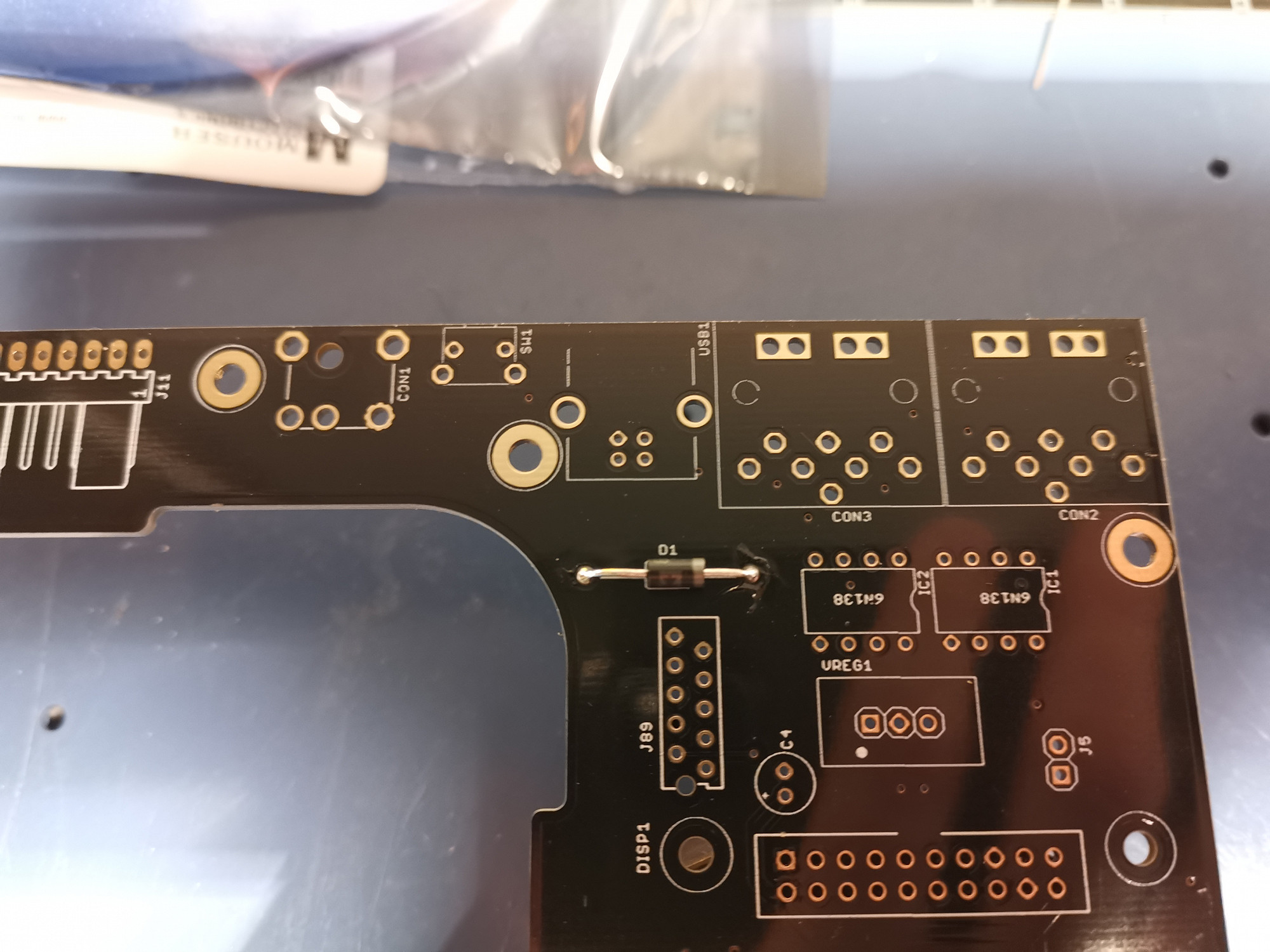
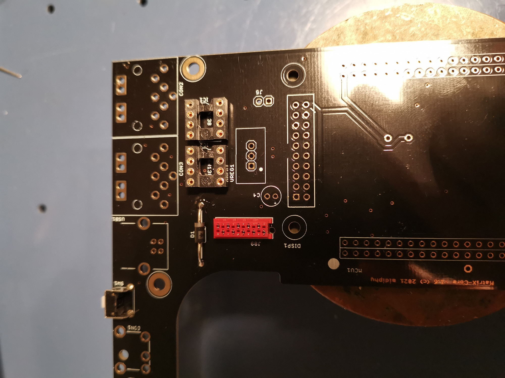
Solder D1 observing polarity.
Note: The 1N5818 diode looks different than the one in the picture, please make sure you solder the correct parts
Solder in the Schottky diode, make sure to align the marking on the diode with the marks on the PCB, so that the polarity is correct.
Solder D1 observing polarity.
Note: The 1N5818 diode looks different than the one in the picture, please make sure you solder the correct parts
Solder in the Schottky diode, make sure to align the marking on the diode with the marks on the PCB, so that the polarity is correct.
1.8 RESET SWITCH
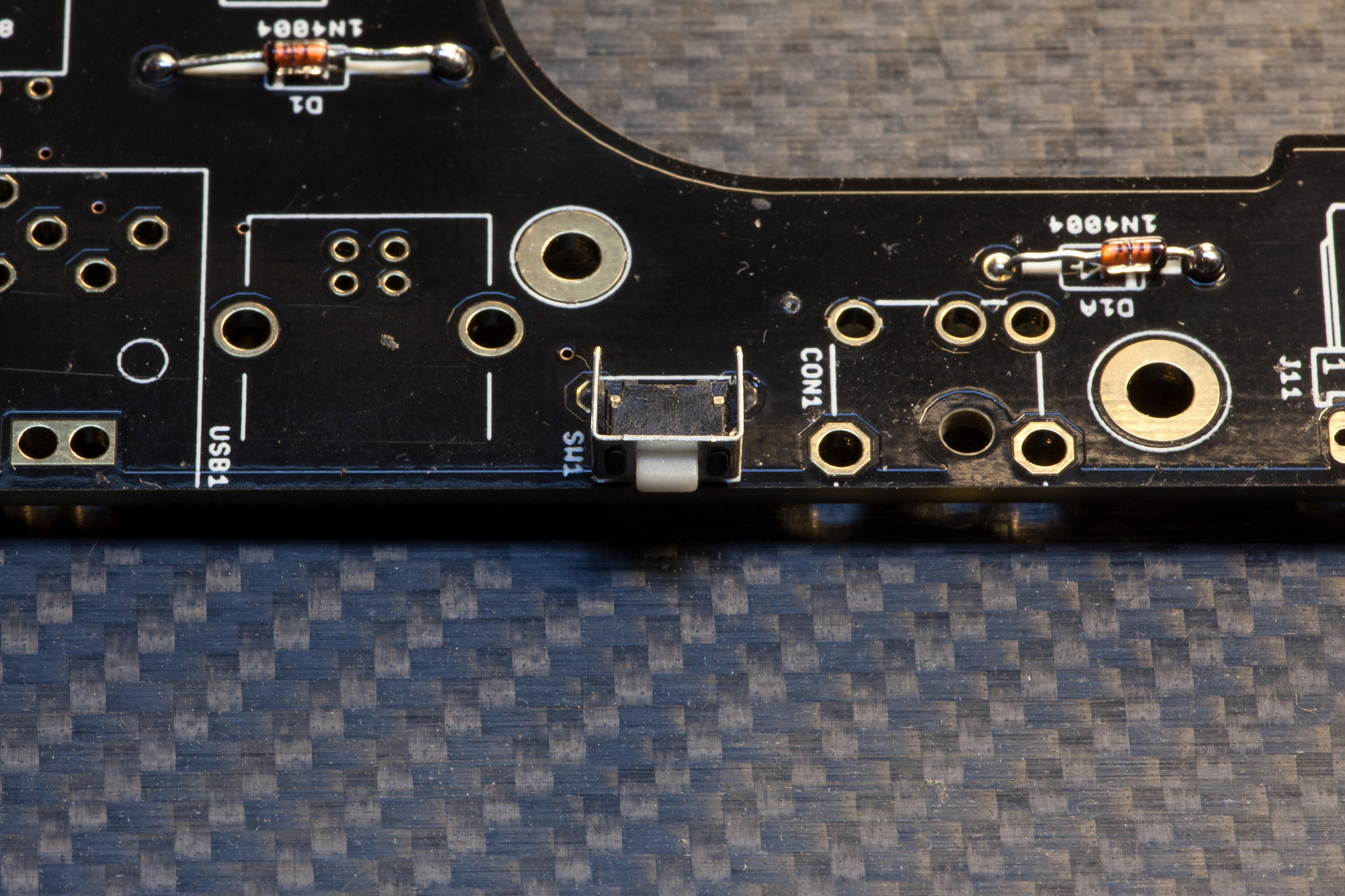
Solder SW1, checking vertical alignment before soldering.
Insert the small reset switch and press it firmly to the PCB to ensure that it sits perfectly on the PCB before soldering. You could also solder a single pin first, then turn the PCB over and push the switch again flat to the PCB while soldering the pin, to make sure it is perfectly aligned.
1.9 Micromatch Connectors
Solder J89 and J44.
Insert the 8-pin and 10-pin PCB micromatch PCB connectors and solder them. Certain parts have a notch only on one short side, which must be aligned with the unplated hole. Other parts have notches on both short sides, so the orientation doesn't matter.
Solder J89 and J44.
Insert the 8-pin and 10-pin PCB micromatch PCB connectors and solder them. Certain parts have a notch only on one short side, which must be aligned with the unplated hole. Other parts have notches on both short sides, so the orientation doesn't matter.
1.10 IC1/IC2 Sockets
Solder IC1/IC2 sockets, observing alignment.
These 8-pin sockets will later contain the MIDI port optocouplers - make sure you align the notch of the IC socket with the notch printed on the PCB.
Solder IC1/IC2 sockets, observing alignment.
These 8-pin sockets will later contain the MIDI port optocouplers - make sure you align the notch of the IC socket with the notch printed on the PCB.
1.11 MCU Headers
Solder MCU1 headers, checking alignment.
Make sure these are angled at an exact 90° angle and sit flat on the PCB before soldering, otherwise inserting the MCU later on will be difficult. To check, you can solder one pin on each header first and then look at the PCB from the side - if they are not at a 90° angle to the PCB, you can adjust it now. Afterwards solder all 100 pins carefully and check them for unwanted solder bridges after soldering.
1.12 Power Distribution Header
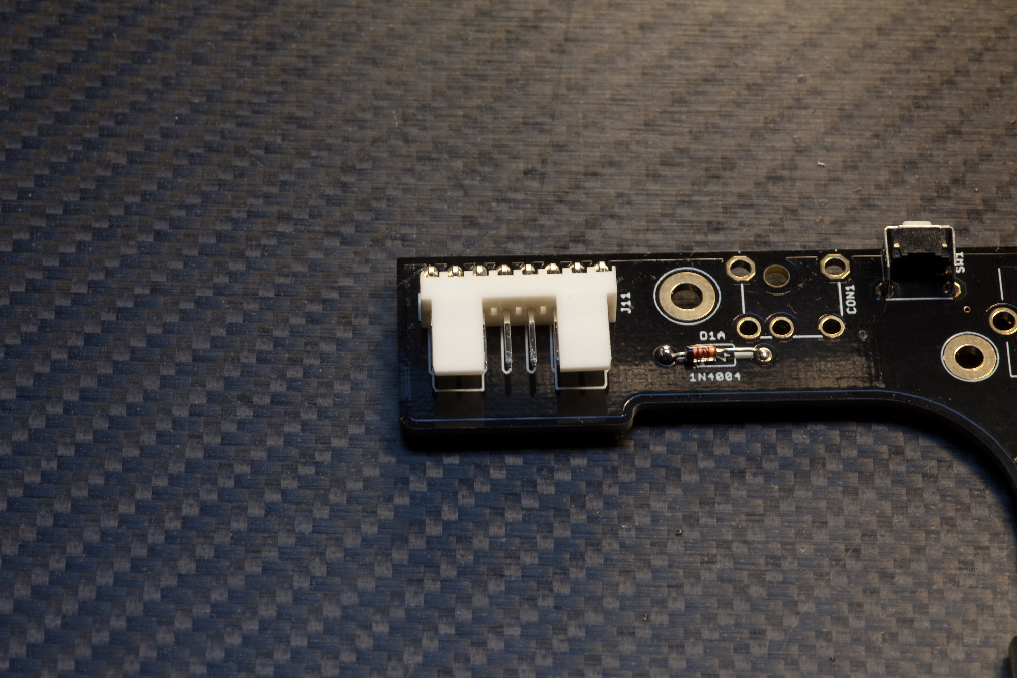
Solder J11.
Make sure you align the header with the silkscreen correctly and then solder it.
Solder J11.
Make sure you align the header with the silkscreen correctly and then solder it.
1.13 Display Header
Solder DISP1 Header, checking alignment.
Make sure that the header is soldered at an exact 90° angle to the PCB surface - you can solder one pin first and view the header from the side to make sure the alignment is correct before soldering all the other pins.
Solder DISP1 Header, checking alignment.
Make sure that the header is soldered at an exact 90° angle to the PCB surface - you can solder one pin first and view the header from the side to make sure the alignment is correct before soldering all the other pins.
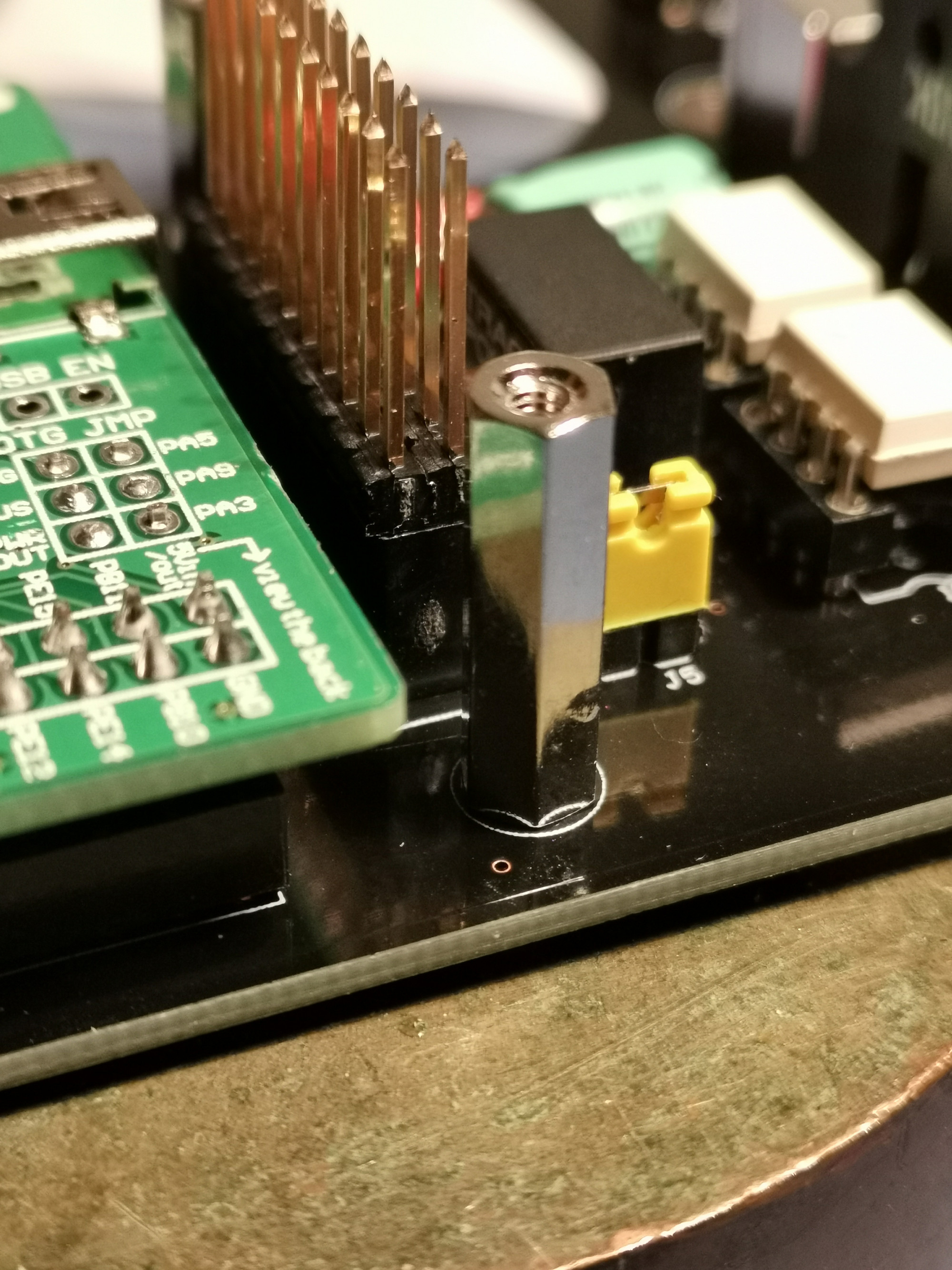
1.14 Standard Pinheaders
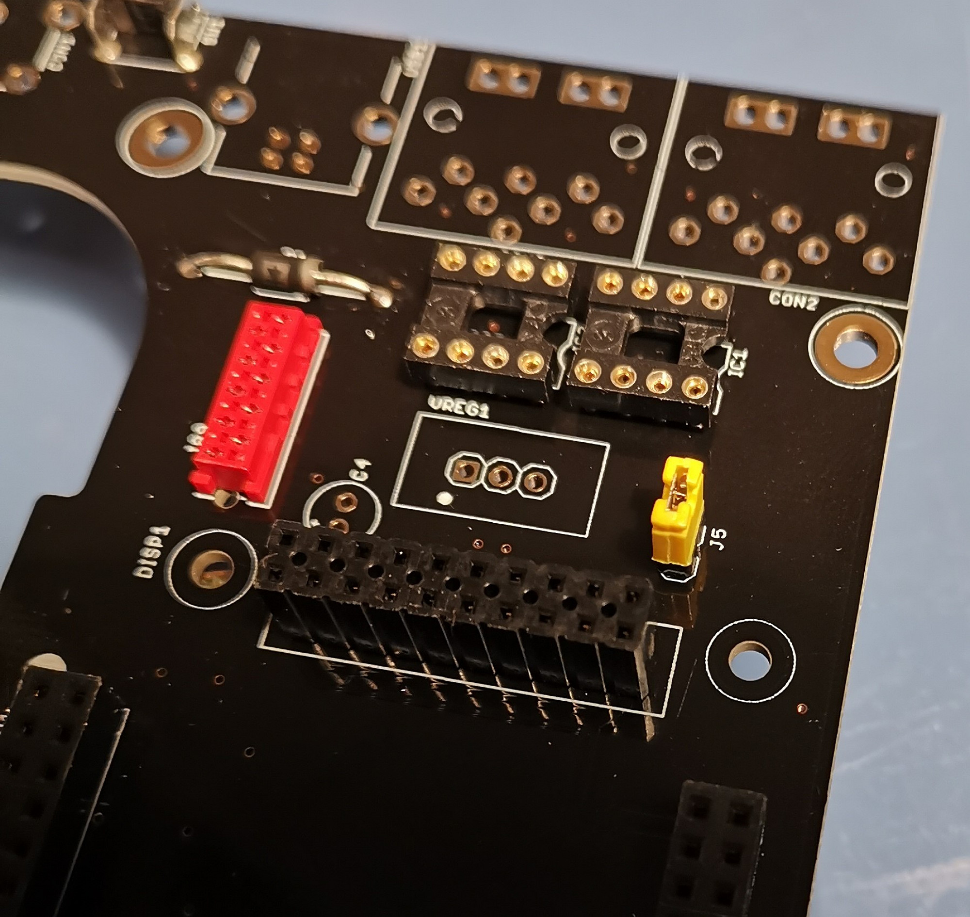
Solder J5 (and optionally JPA0).
Install and solder a 2-pin header in J5 - you can also install a 2-pin header in JPA0 if you plan to do software development for the MatriX and think you would require the "bootloader hold" option - for normal MatriX uses, populating JPA0 is not recommended.^
If installing pinheader JPA0, put it on the top of the board. It is also possible to simply bridge the header pins e.g. with tweezers if required to enter boot hold
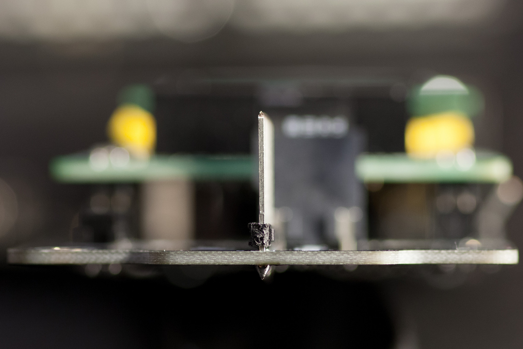
1.15 Voltage Regulator
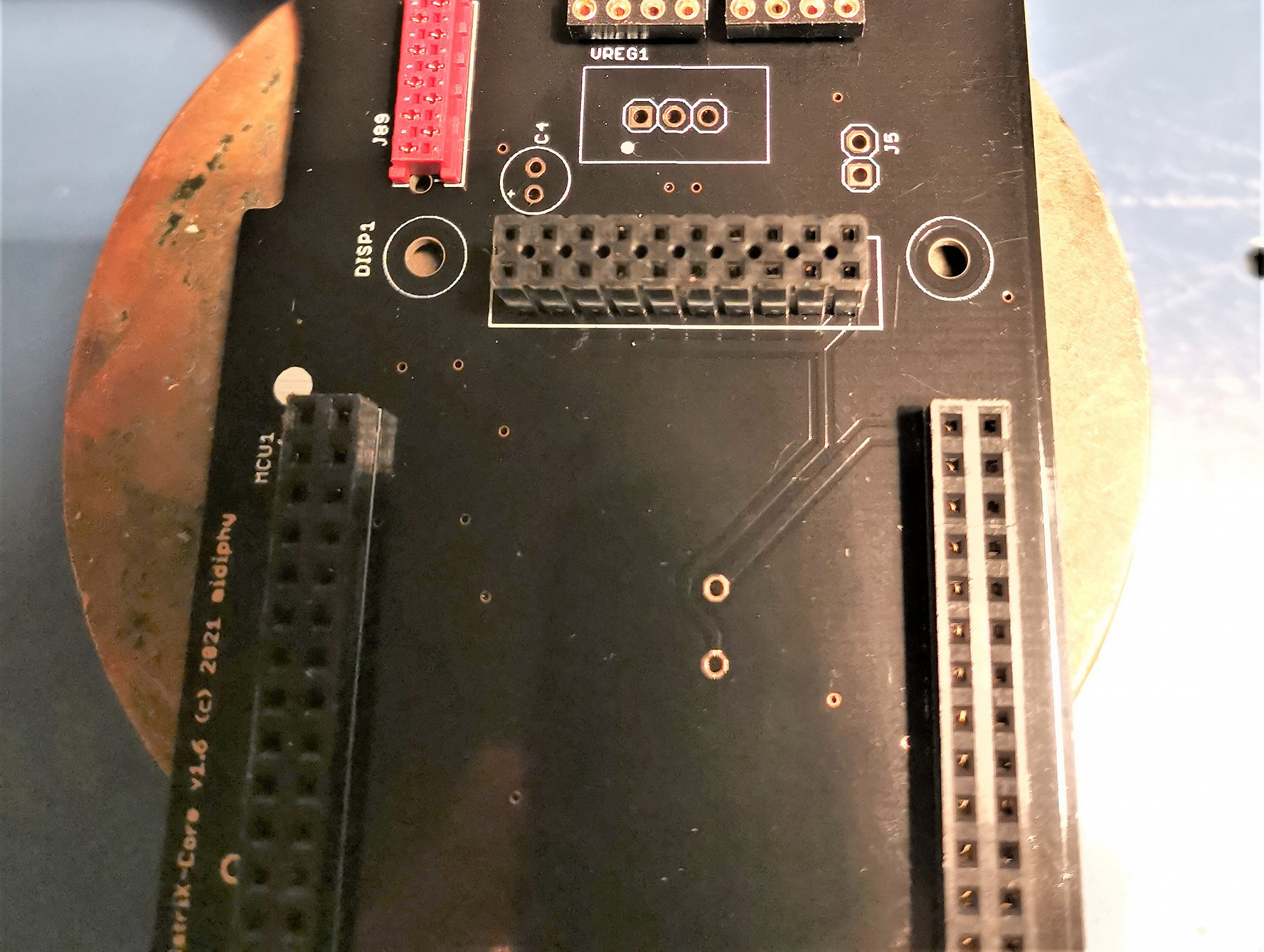
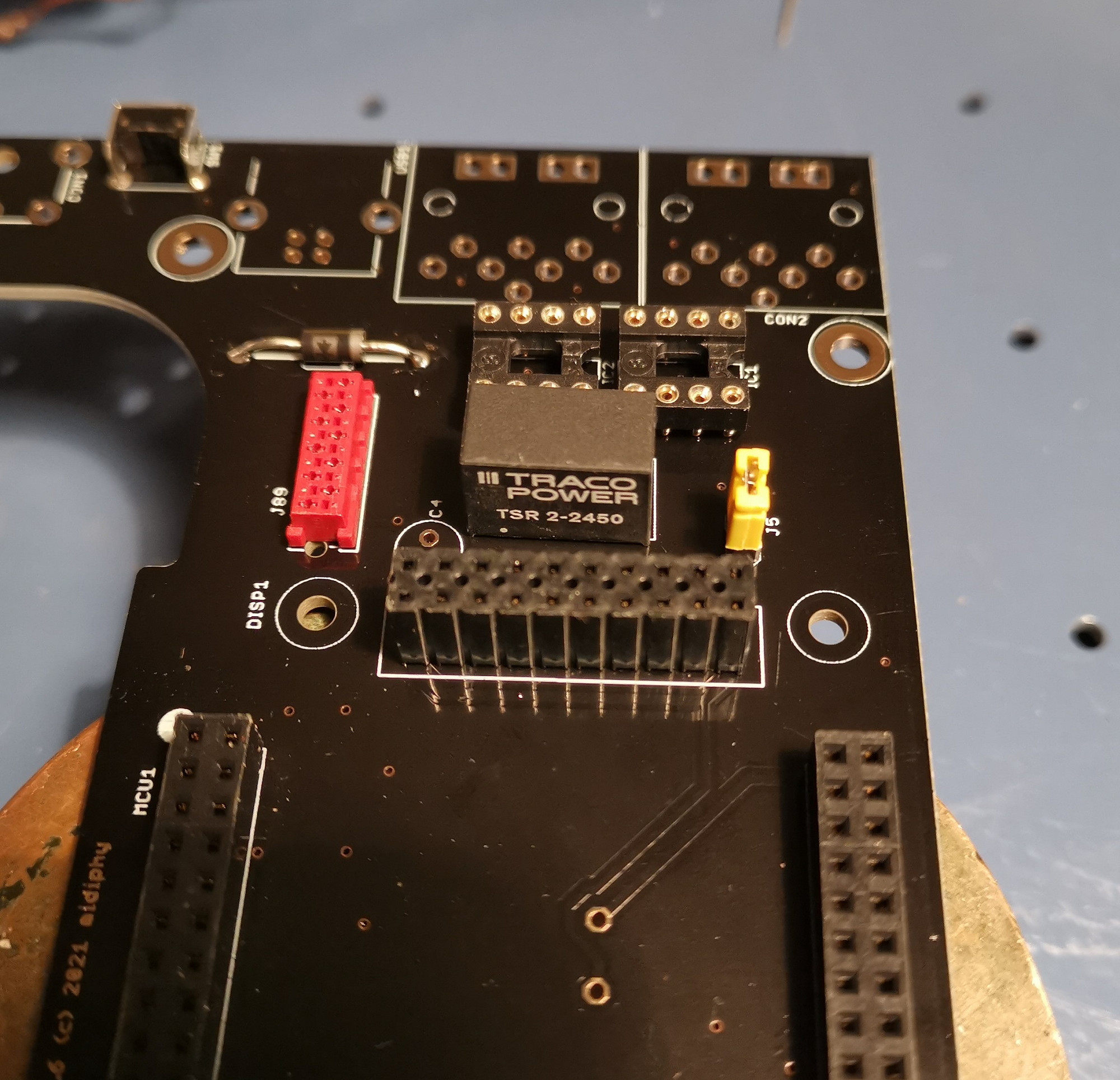
Solder VREG1.
Align the dot of the regulator with the one on the silkscreen. It is necessary to clip the bottom leads shorter after soldering.
Solder VREG1.
Align the dot of the regulator with the one on the silkscreen. It is necessary to clip the bottom leads shorter after soldering.
1.16 Rear-Panel Connectors
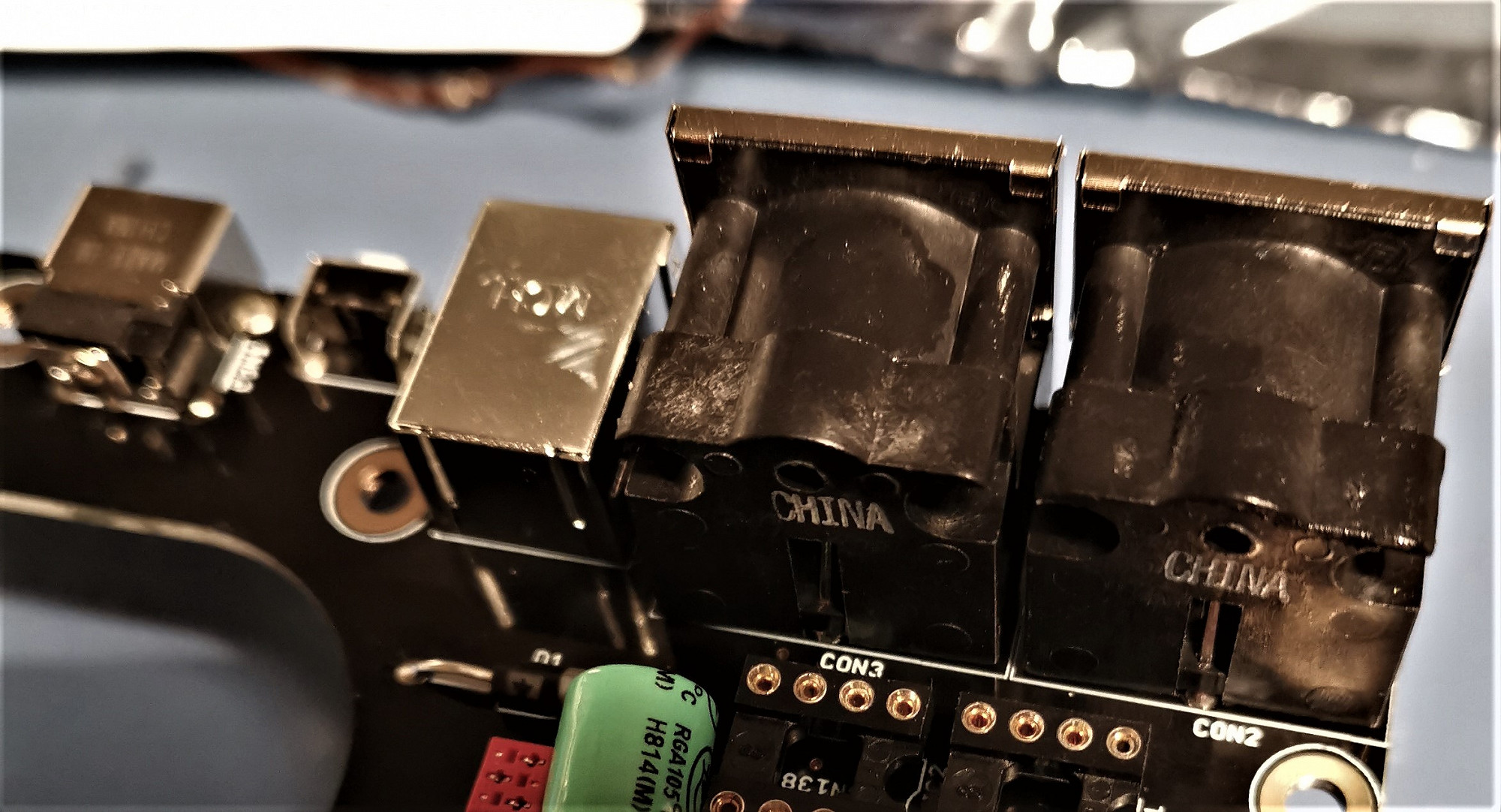
Solder CON1-3 and USB1.
Make sure they sit flat on the PCB - you can do that by soldering one pin first, then turning the PCB over, and pushing it firmly on the PCB while heating up that "tacked" pin. Then solder the remaining pins.
Before committing to soldering all pins of a connector, check again that everything is flat!
1.17 Electrolytic Capacitor
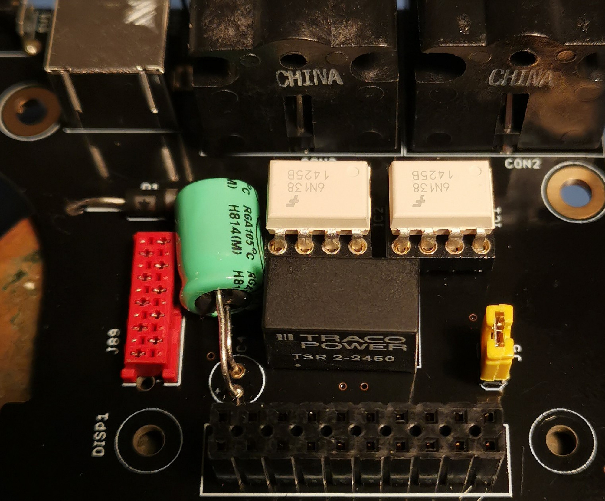
Solder C4, observing polarity.
There is a small "+" marking on the PCB - insert the electrolytic capacitor so, that the marked side ("-") goes into the other hole - see picture. The "+" leg is typically longer.
Note my capacitor is a random one out of the drawer and is quite a lot larger than the one specified in the BOM. The correct one should fit properly :)
1.18 MICRO SD-CARD HOLDER
Solder SOCK1.
Place the MicroSD-Card holder on the PCB, solder the stabilizing pins first, then solder the small data pins. After soldering, check for unwanted bridges.
Solder SOCK1.
Place the MicroSD-Card holder on the PCB, solder the stabilizing pins first, then solder the small data pins. After soldering, check for unwanted bridges.
1.19 Install Optocouplers
Install IC1/IC2, checking alignment.
You might need to slightly bend/straighten the IC legs before they fit in the IC sockets. Make sure to align the marking/dot on the optocouplers with the notches on the IC sockets.
Install IC1/IC2, checking alignment.
You might need to slightly bend/straighten the IC legs before they fit in the IC sockets. Make sure to align the marking/dot on the optocouplers with the notches on the IC sockets.
1.20 PREPARE MCU
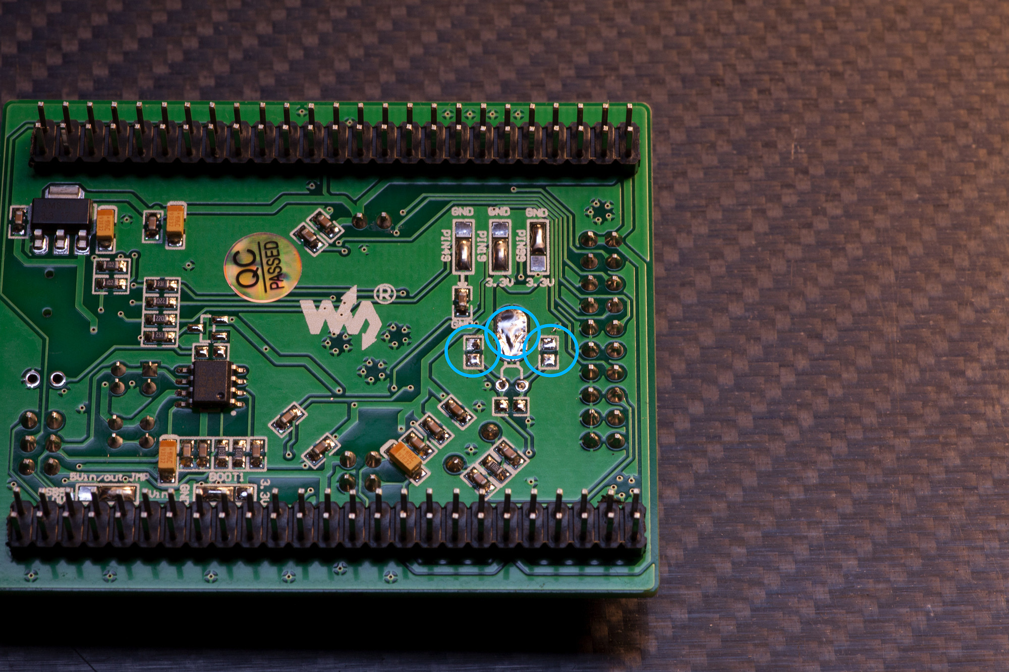
Remove crystal and assorted capacitors on MCU board.
Turn over the Waveshare MCU and find the locations marked in the image. Snip off the two crystal pins and desolder it from the PCB. Also remove the neighboring two capacitors - this is most easily done by heating up one pin, then the other pin with your soldering iron and then just "dragging off" the capacitor with the soldering iron.
Check the BOOT1 jumper setting. This should be jumpered to 0V (GND). If it happens to be bridged to 3v3, disconnect this bridge and connect the center pad to 0V (GND).
1.21 MCU CONFIG
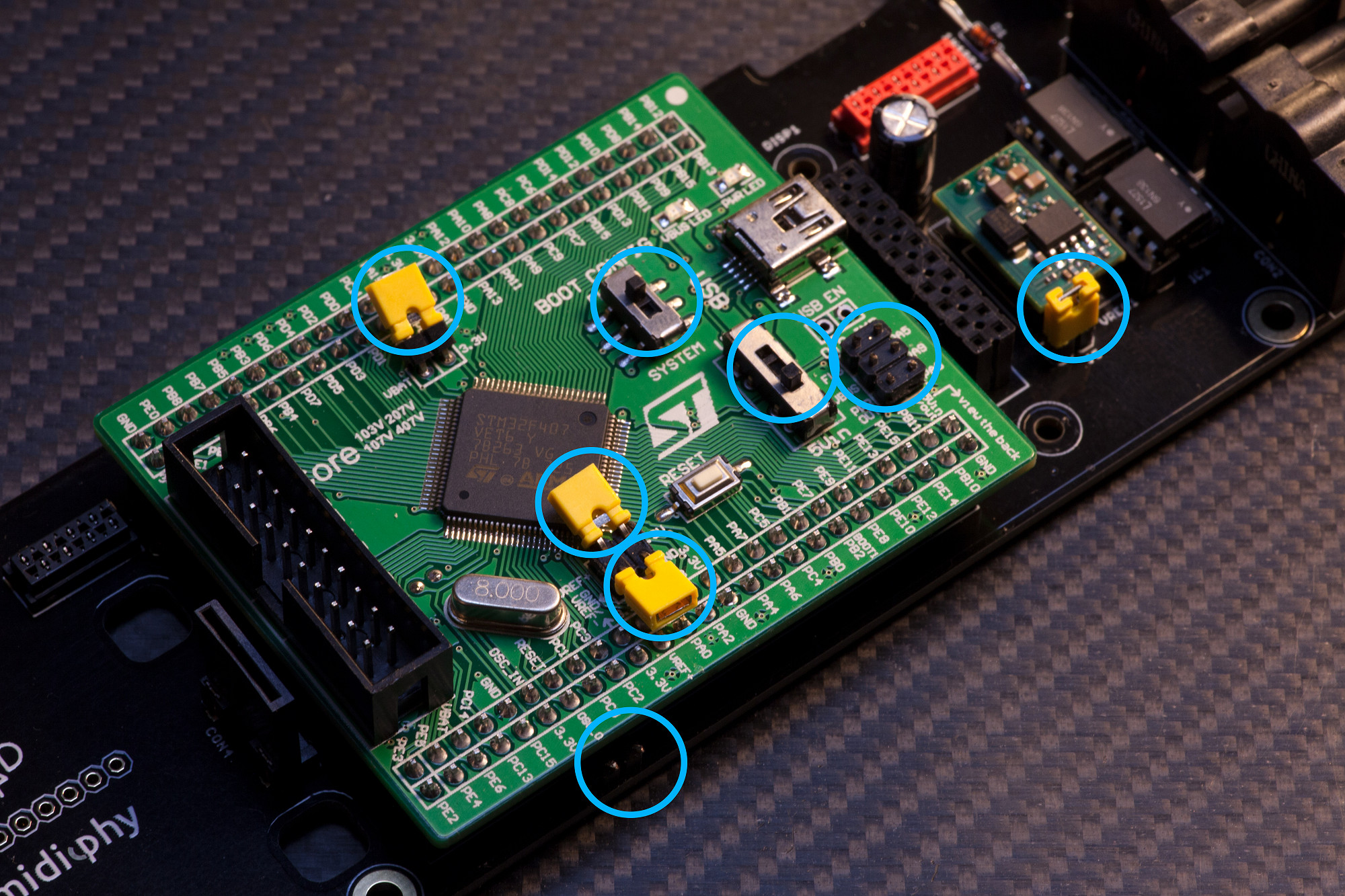
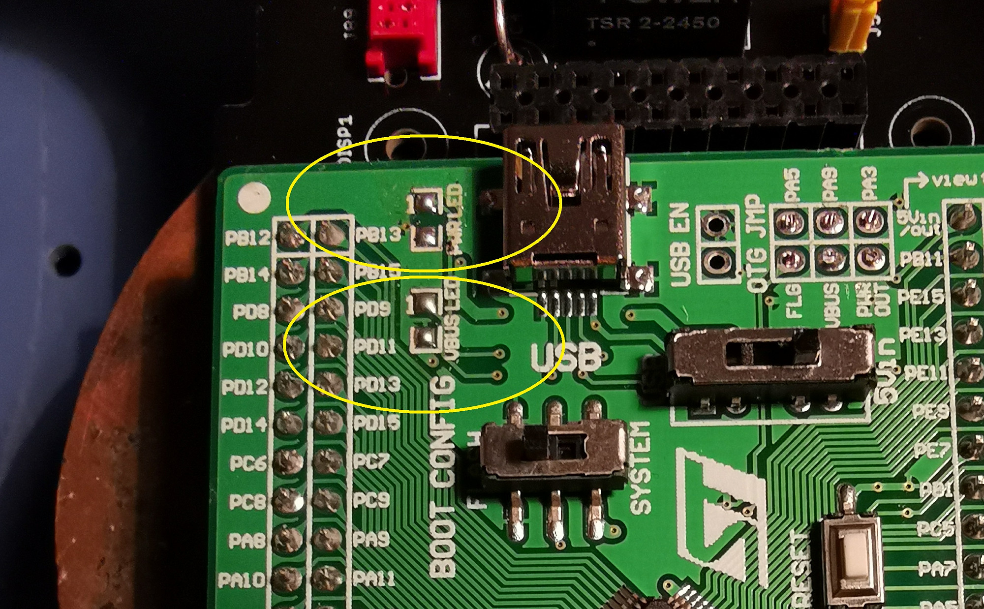
Please thoroughly follow these steps, points of interests are highlighted in the image:
If you installed a JPA0 header before, bend it slightly to the side, so that it does not interfere with the MCU board.
On the front of the MCU board, desolder or otherwise remove the two LEDs marked "VBUS" and "PWR"
Align the dot on the MCU board with the dot on the PCB and then push the MCU onto the core PCB. This process may require some physical force, but make sure you don't bend any pins - i.e. apply linear pressure from all four corners of the PCB. The MCU board must go in nearly all the way, or the display won't fit - a remainder of less than 1mm of visible MCU headers is normal (i.e. the MCU sockets are low-profile and the last half millimeter of headers won't fit in).
Remove the three yellow jumpers on the right side of the MCU labeled FLG, VBUS and PWR OUT and snip those pins as close as possible to the PCB.
Move the two slide switches to the selections: "Boot Config: Flash" and "Power: 5V In".
Temporarily remove the three remaining other yellow jumpers on the left side of the MCU, bend the pins in a 75° angle (not completely flat) towards the PCB, turn over the jumpers and install them "upside-down" to make sure they have a perfect contact. If there is no proper contact, you may need to bend the pins further apart before installing the jumpers.
Install one of the removed jumpers on J5 of the MatriX Core PCB.
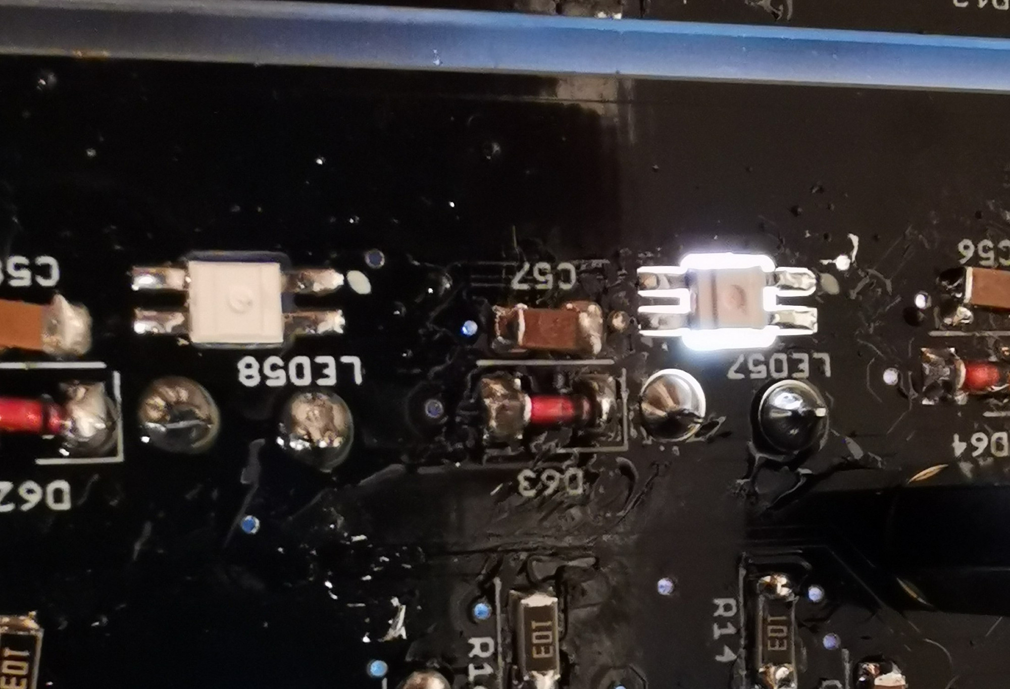
1.22 Remove or hide LEDs on Waveshare board
Either desolder or simply clip off the red SMT LEDs. Otherwise they might shine through the panel later.
Either desolder or simply clip off the red SMT LEDs. Otherwise they might shine through the panel later.
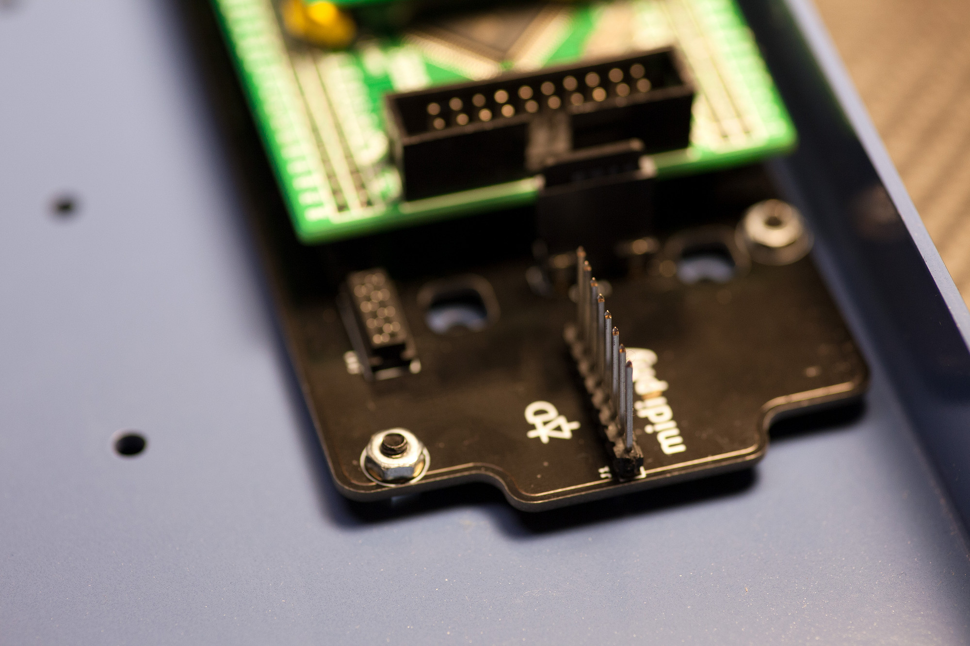
1.23 Solder Headers to Axes PCB
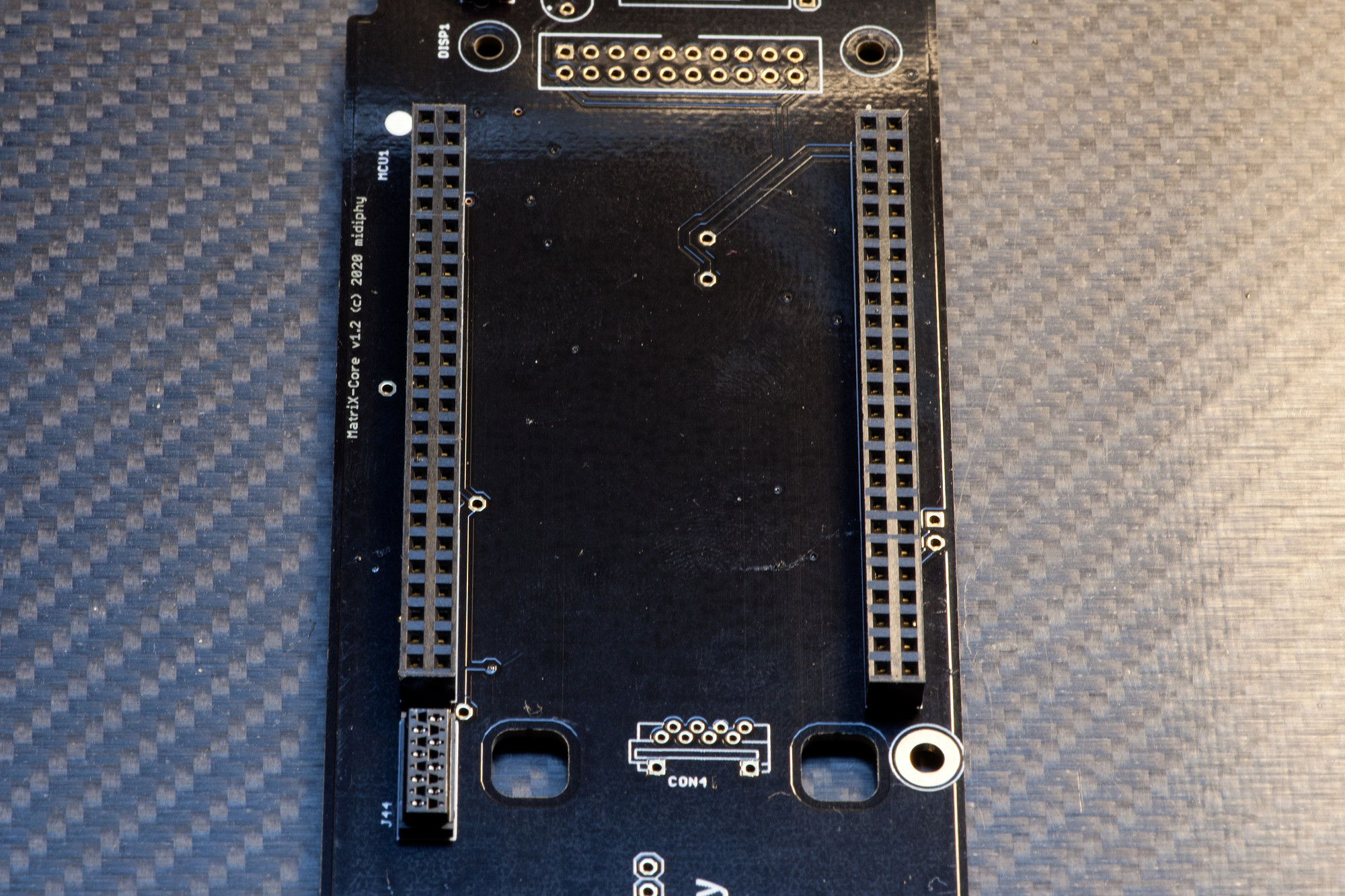
Solder header, checking alignment
Insert the header and "tack"/solder a single pin at first. This way you can easily correct the alignment of the header. While heating the "tacked" pin from the underside you can carefully adjust the header to be exactly upright - installed at a precise 90° angle to the PCB. When you are happy with the result, solder the remaining pins.
Clip off the protruding tails on the bottom of the Core PCB. Clearance is 3mm.
1.24 Display installation
Solder OLED on headers and fasten with 18mm hex spacers
Screw in the M2.5x18 hex spacers with M2.5 screws from the bottom of the core PCB
Cut the display headers from the BOM to size (2x10 pins)
Insert the 2x10 header so the plastic base rests on the socket
Put the OLED on top of the headers (check the alignment) and mount the M2.5 screws.
Carefully cut the top of the OLED headers very short with a side cutter - Important: the cut headers must be lower than the top plane of the OLED, as the screen protector will also sit on top of them
Finally carefully solder all top header pins while not touching the OLED with your soldering iron tip - solder from the side away from the OLED and leave the display protection foil on the OLED while soldering
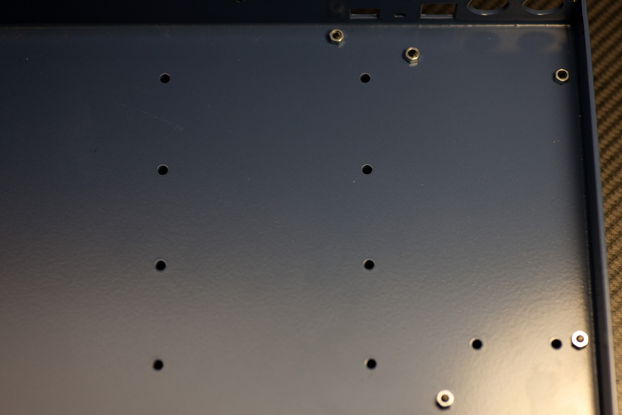
1.25 Prepare Core PCB installation in Case
Install spacing nuts
Remove the white case top and plate and store all screws in a safe place.
Prepare five 10mm M3 screws as shown in the picture, put 3mm nuts on top of the screws, but don't fasten the nuts yet - as shown in the picture.
Install spacing nuts
Remove the white case top and plate and store all screws in a safe place.
Prepare five 10mm M3 screws as shown in the picture, put 3mm nuts on top of the screws, but don't fasten the nuts yet - as shown in the picture.
1.26 Install Core PCB in case
Fasten Core PCB
While lifting the case with one hand, you can insert the Core PCB in its final location. Make sure the small reset switch is nicely aligned with its case hole and that the DIN8 ports are sitting flush at the backside of the case. While pushing down the Core PCB, use a screwdriver to "fasten" the M3 spacing nuts - the Core PCB pushed from the top will give enough friction so that the nuts will finally lock firmly against the case bottom. Finally fasten the five screws from the top with an additional five M3 nuts.
After installation, the PCB should be fixed safely in place and should not wiggle anymore.
1.27 Install MatriX firmware using MIOS Studio
Update the installed MIOS bootloader to the full MatriX app
Before starting the software installation, power your MatriX core with the 12V PSU. To do that, just plug in the cable in the 12V barrel connector and then connect it to your computer via a USB cable. You will need an up-to-date version of MIOS Studio, that you can get .
The installation is identical to the software installation you performed for your SEQ v4+ or LoopA, just use the newest MatriX app release available on the .
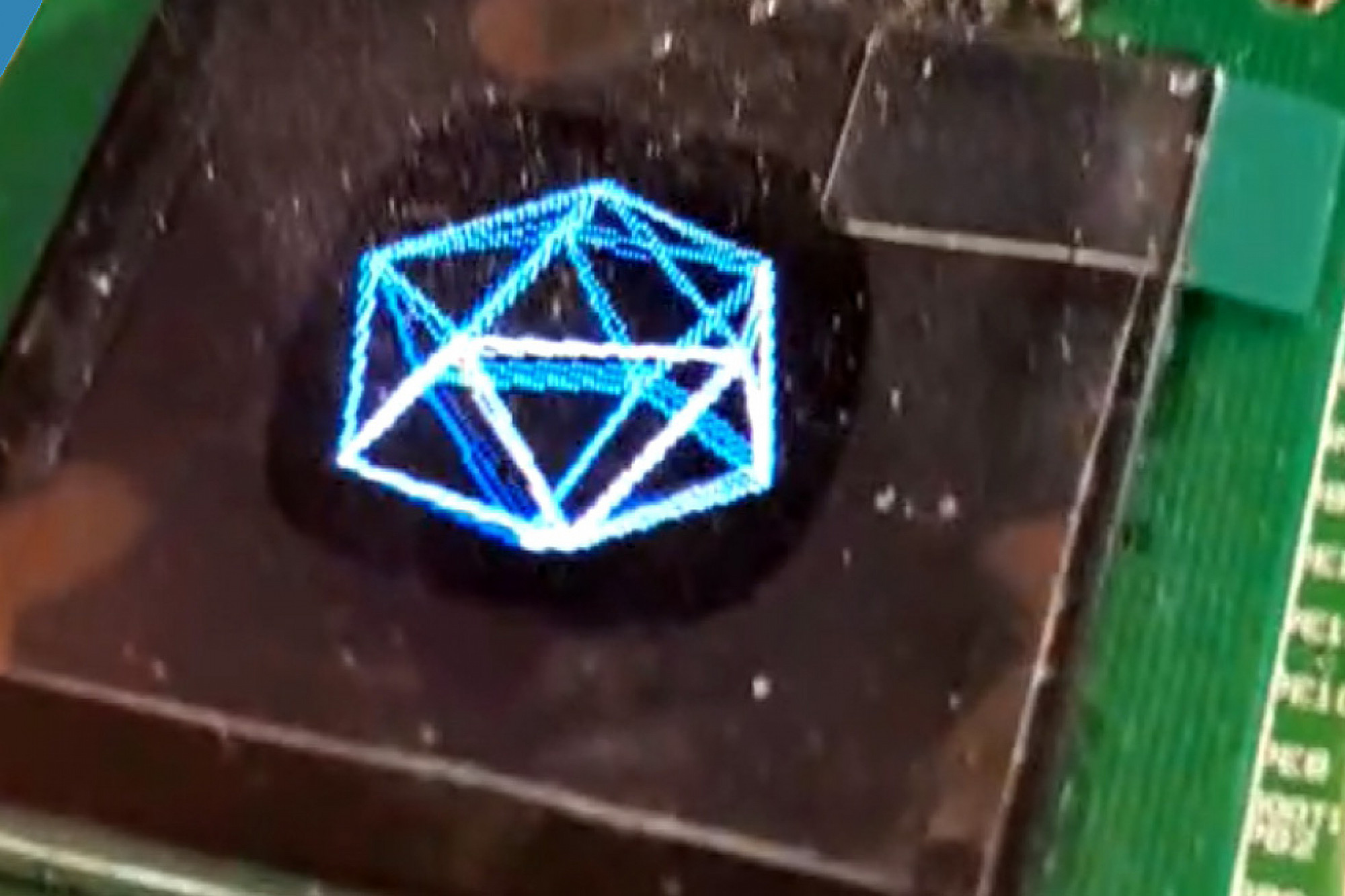
is a short video tutorial for the installation of the software on the SEQ v4+, just perform the same steps for your MatriX core.
After the app is installed and if you have not installed any MicroSD card yet, you should be greeted by the MatriX test mode - well done and enjoy! :)
Update the installed MIOS bootloader to the full MatriX app
Before starting the software installation, power your MatriX core with the 12V PSU. To do that, just plug in the cable in the 12V barrel connector and then connect it to your computer via a USB cable. You will need an up-to-date version of MIOS Studio, that you can get .
The installation is identical to the software installation you performed for your SEQ v4+ or LoopA, just use the newest MatriX app release available on the .
is a short video tutorial for the installation of the software on the SEQ v4+, just perform the same steps for your MatriX core.
After the app is installed and if you have not installed any MicroSD card yet, you should be greeted by the MatriX test mode - well done and enjoy! :)
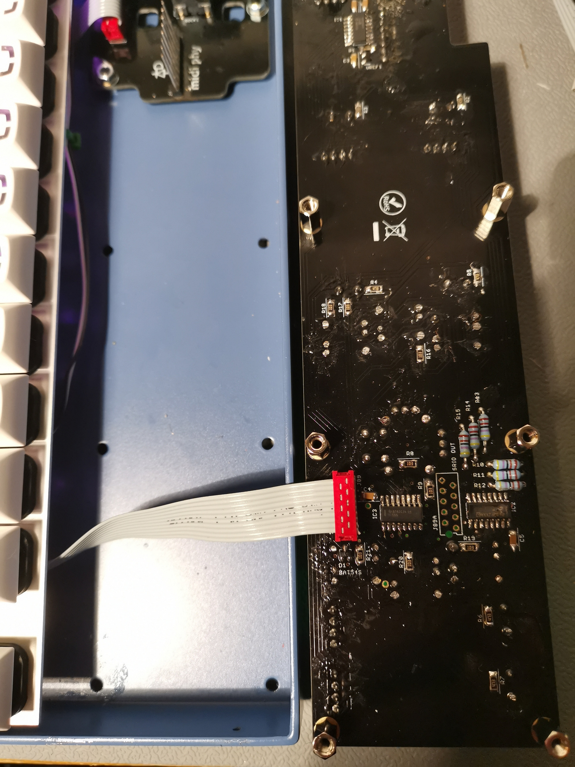
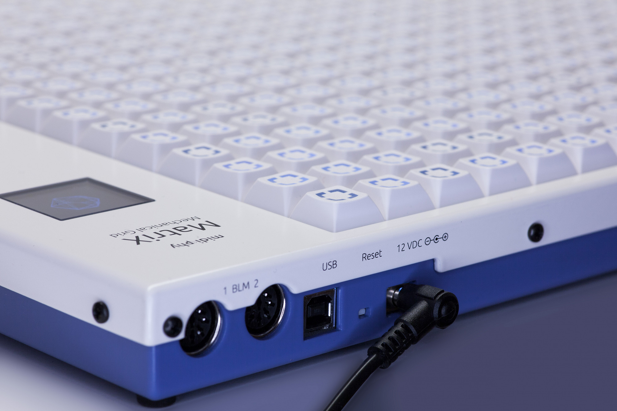
1.28 Test bidirectional MIDI (BLM) connection to a SEQ v4+ or LoopA)
Make sure no micro SD card is inserted, so your MatriX will boot up in test mode.
Now connect a DIN MIDI cable to any MatriX BLM port to test this port. Connect the other end of the cable to the respective BLM port of a SEQ v4+ or LoopA. A normal DIN5 cable may be used as long as all connectors are wired through. We have found that some DIN connectors are too thick to fit properly when the case top is attached. Options here are to:
use DIN cables with a longer metal barrel
build or modify cables using slimmer DIN plug (such as most metal plugs)
trim back plastic connectors slightly
If you are using a SEQ v4+, then it must be configured to send to the BLM on OUT4 and receive on IN4.
If you are using a LoopA, you can just use the BLM connector on its backside - make sure you upgrade to the newest LoopA firmware revision first and also make sure that the MatriX is enabled in LoopAs setup screen.
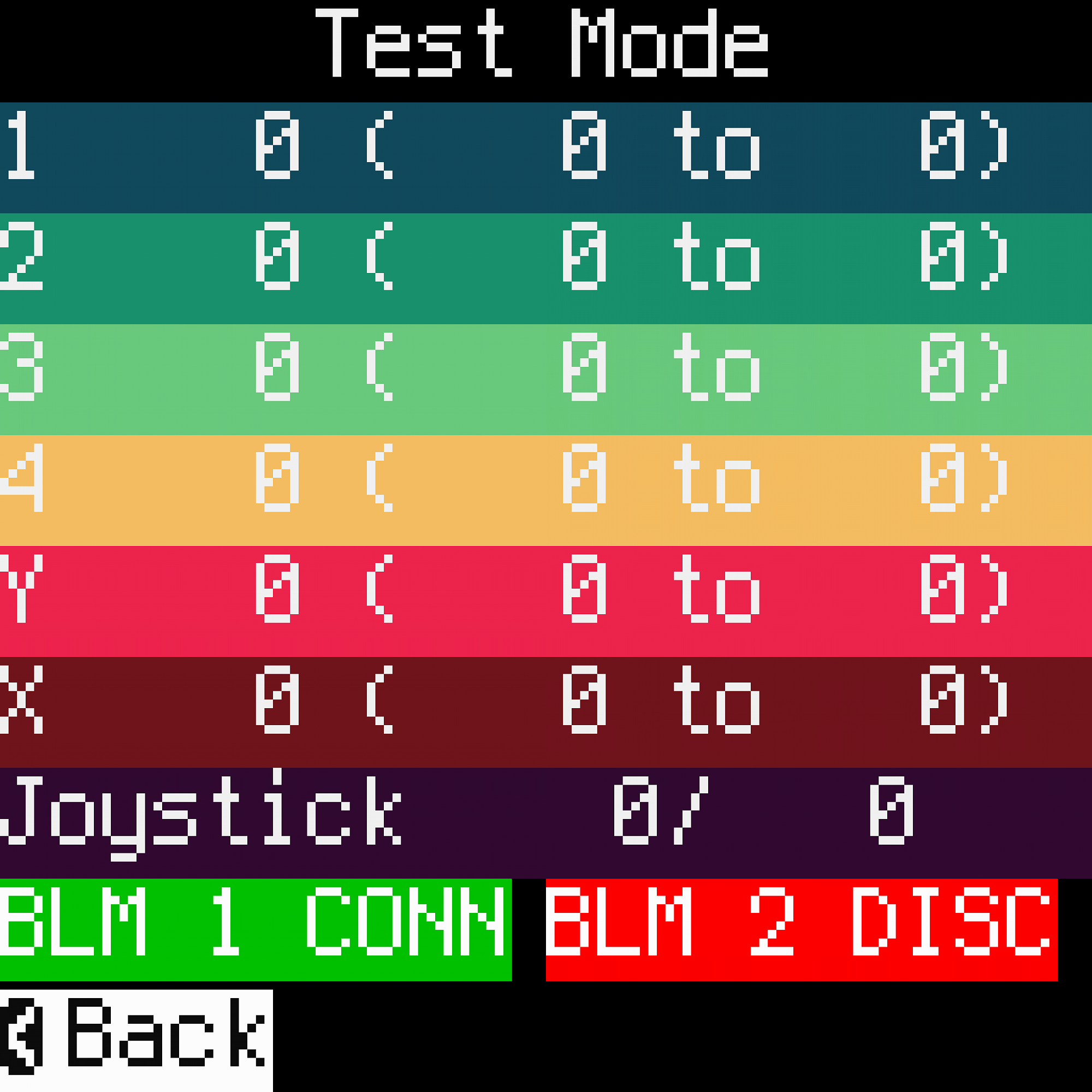
The test screen will show once communications are established between two devices, this allows to test both BLM1 and BLM2 ports individually. If the respective BLM1/2 label lights up in green, a bidirectional connection is established and the port is confirmed working.
For troubleshooting, the SMT components responsible for MIDI signals are located near or under the DIN ports/optocouplers and additionally resistors R13/R18.
Make sure no micro SD card is inserted, so your MatriX will boot up in test mode.
Now connect a DIN MIDI cable to any MatriX BLM port to test this port. Connect the other end of the cable to the respective BLM port of a SEQ v4+ or LoopA. A normal DIN5 cable may be used as long as all connectors are wired through. We have found that some DIN connectors are too thick to fit properly when the case top is attached. Options here are to:
use DIN cables with a longer metal barrel
build or modify cables using slimmer DIN plug (such as most metal plugs)
trim back plastic connectors slightly
If you are using a SEQ v4+, then it must be configured to send to the BLM on OUT4 and receive on IN4.
If you are using a LoopA, you can just use the BLM connector on its backside - make sure you upgrade to the newest LoopA firmware revision first and also make sure that the MatriX is enabled in LoopAs setup screen.
The test screen will show once communications are established between two devices, this allows to test both BLM1 and BLM2 ports individually. If the respective BLM1/2 label lights up in green, a bidirectional connection is established and the port is confirmed working.
For troubleshooting, the SMT components responsible for MIDI signals are located near or under the DIN ports/optocouplers and additionally resistors R13/R18.
Chapter 2: Axes PCB
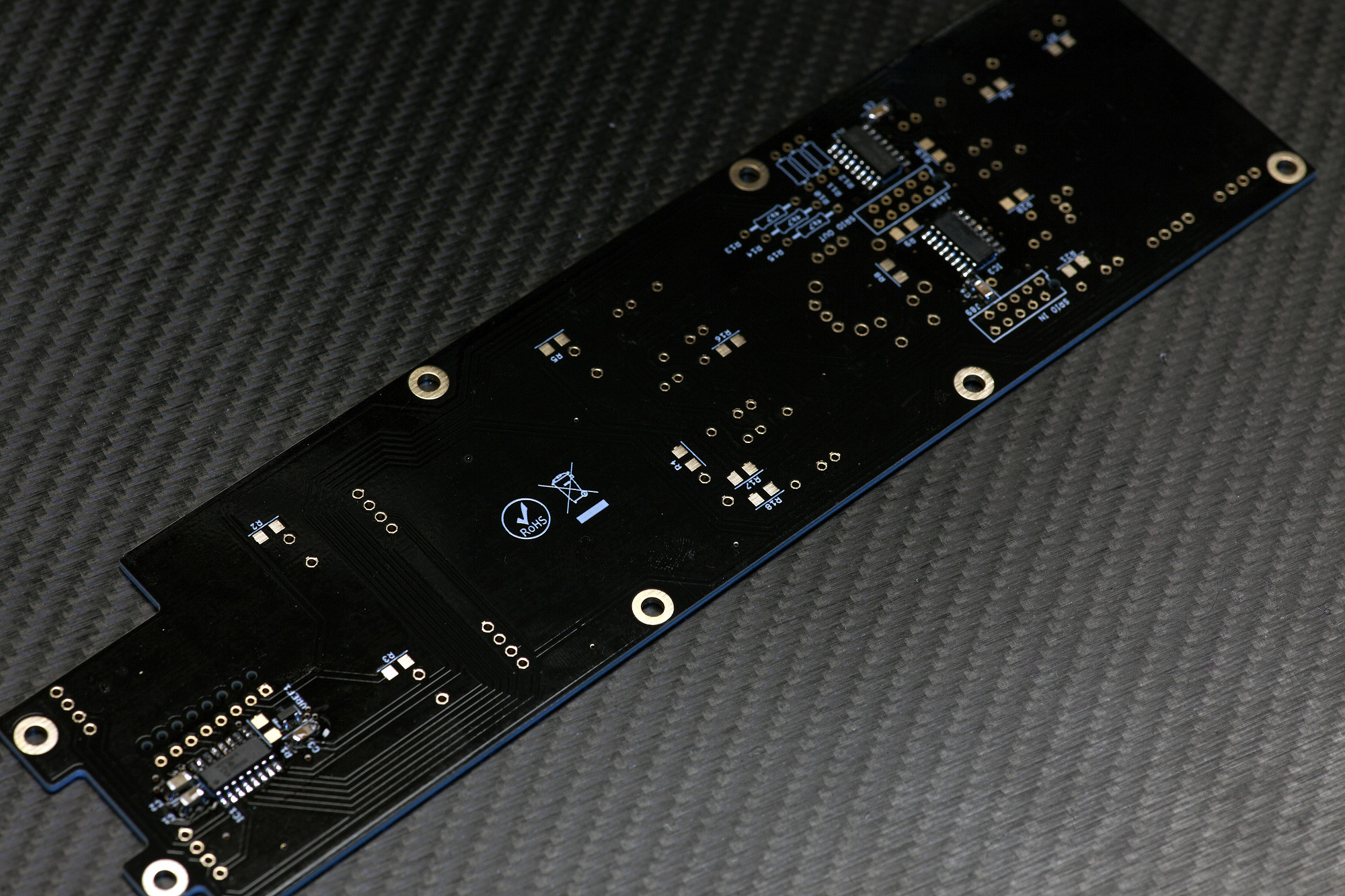
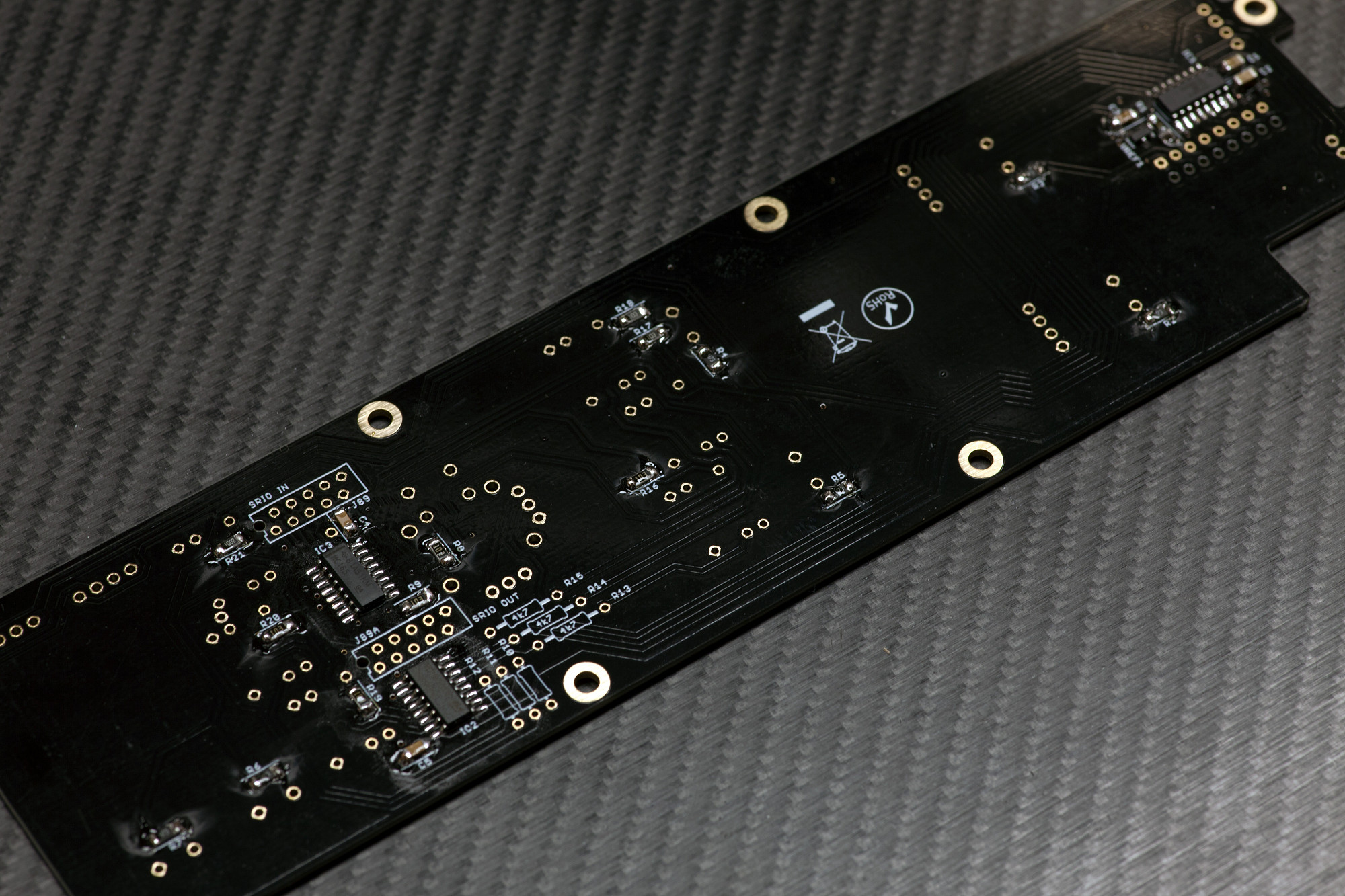
2.1 SMT ICs
Solder SMT IC1-IC3, observing alignment
Just as with the Core PCB, check alignment first (align marking on the IC to printed notch on the silkscreen of the PCB). Then "tack" the ICs by soldering two pins on one side, then drag-solder the other side, then drag-solder the original side. Always check SMT IC pins with a loupe/magnifying glass for unwanted shorts and also that every pin has proper contact with its PCB pad.
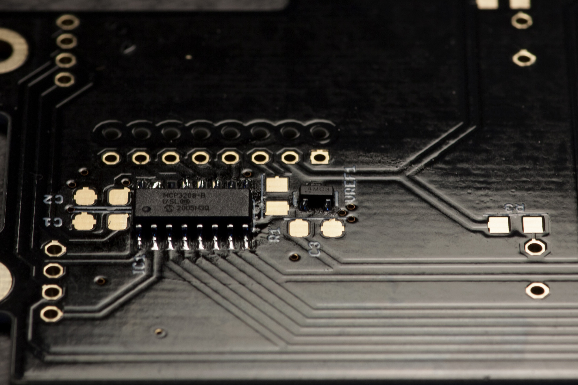
2.2 VOLTAGE REFERENCE
Solder VREF1
This is a small SMT IC, that can only be only soldered in a single orientation, so the alignment will be correct once you've soldered all pins.
Solder VREF1
This is a small SMT IC, that can only be only soldered in a single orientation, so the alignment will be correct once you've soldered all pins.
2.3 SMT CAPACITORS (NON-POLARIZED)
Solder all unpolarized SMT capacitors
These are primarily used for stabilizing the supply voltage of nearby ICs and are not polarized, you can solder them in any orientation.
Solder all unpolarized SMT capacitors
These are primarily used for stabilizing the supply voltage of nearby ICs and are not polarized, you can solder them in any orientation.
2.4 SMT RESISTORS
Solder SMT Resistors
Next, solder all SMT resistors, observing their values.
Solder SMT Resistors
Next, solder all SMT resistors, observing their values.
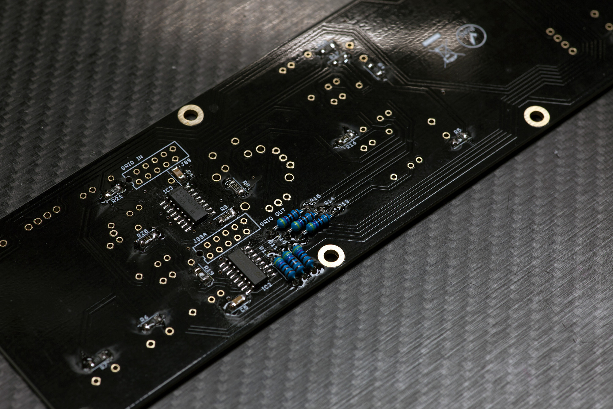
2.5 THT RESISTORS
Solder THT Resistors
Now we can move on to the THT parts, first solder resistors R10-R15.
Solder THT Resistors
Now we can move on to the THT parts, first solder resistors R10-R15.
2.6 Optional, normally not required: solder the BAT54S diode
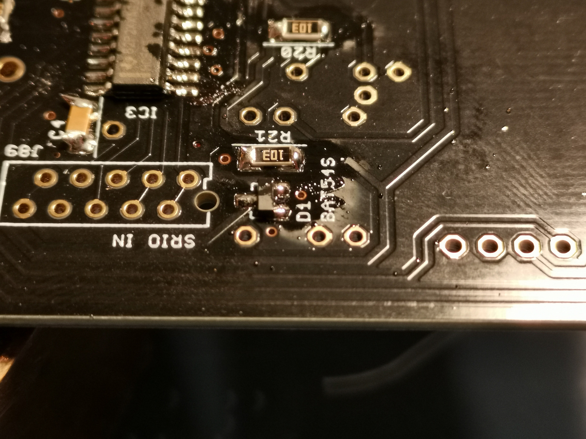
Solder D1
It's a three-pin part and will only fit in in one orientation, see photo.
BAT54S diodes should normally not be required, but if the digital behavior is strange you can try to solder a diode in or simply bridge the three pads with a wire/solder blob. As an explanation: all 0V lines are "star-wired" back to the DC input and 0V is not connected between boards. An antiparallel Schottky would keep the 0V of different domains within a diode drop.
2.7 MICROMATCH CONNECTORS
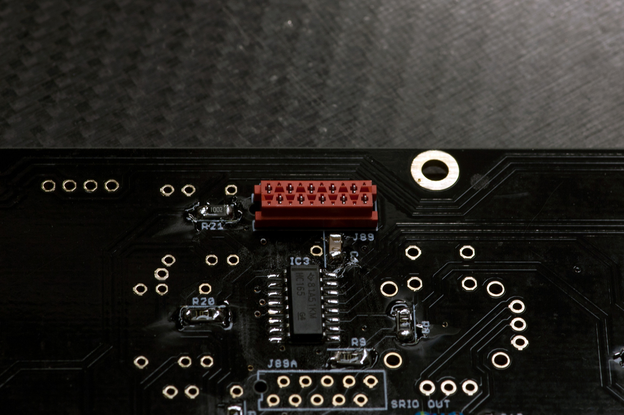
Solder J89
Insert the 10-pin Micromatch connector, turn over the PCB and solder it.
Solder J89
Insert the 10-pin Micromatch connector, turn over the PCB and solder it.
2.8 INTERBOARD CONNECTOR
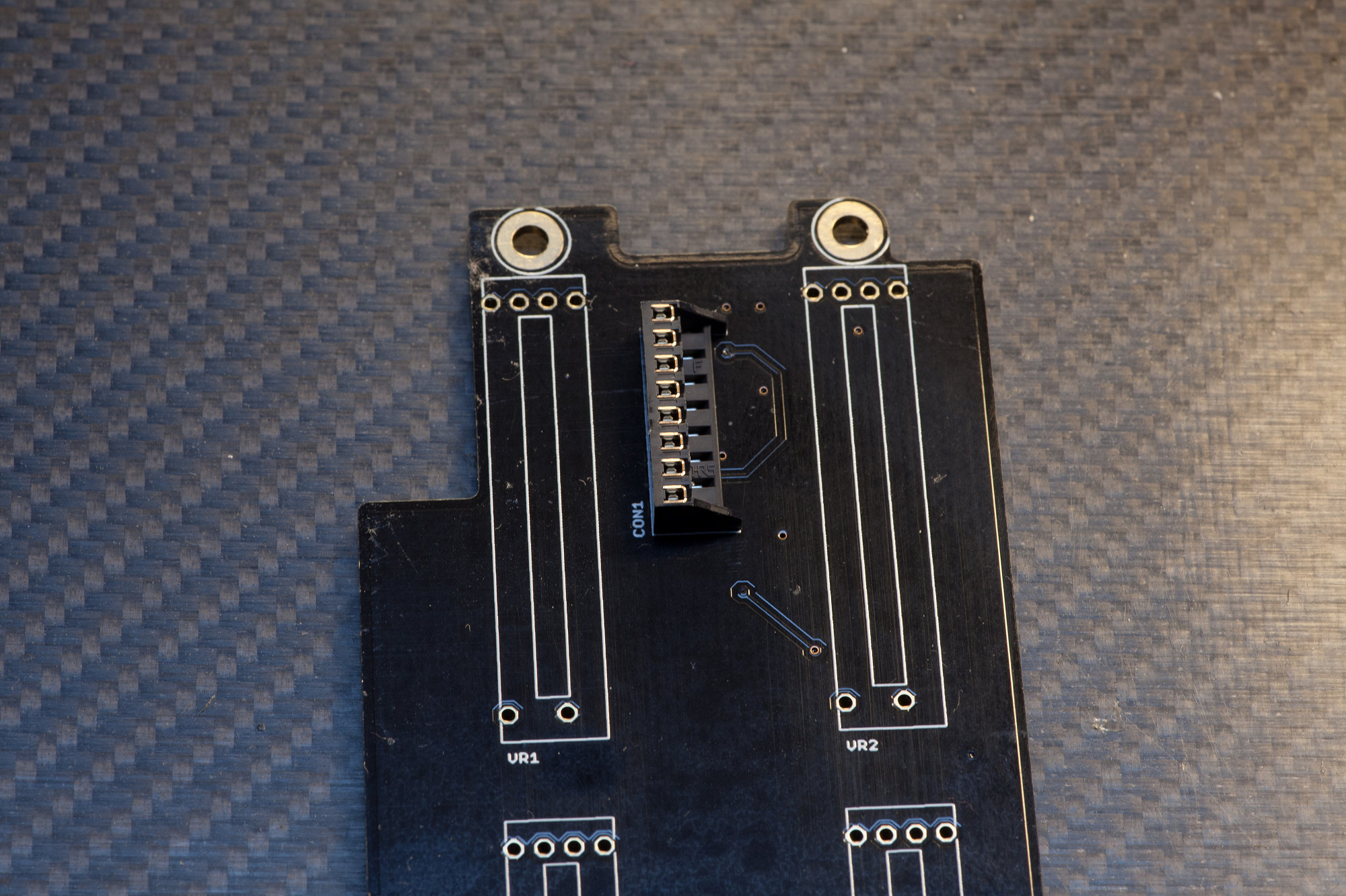
Solder CON1
Align the the through-board headers with the silkscreen, make sure it sits upright at a 90° angle towards the PCB and solder it.
Solder CON1
Align the the through-board headers with the silkscreen, make sure it sits upright at a 90° angle towards the PCB and solder it.
2.9 BEND MEC SWITCH LEDS
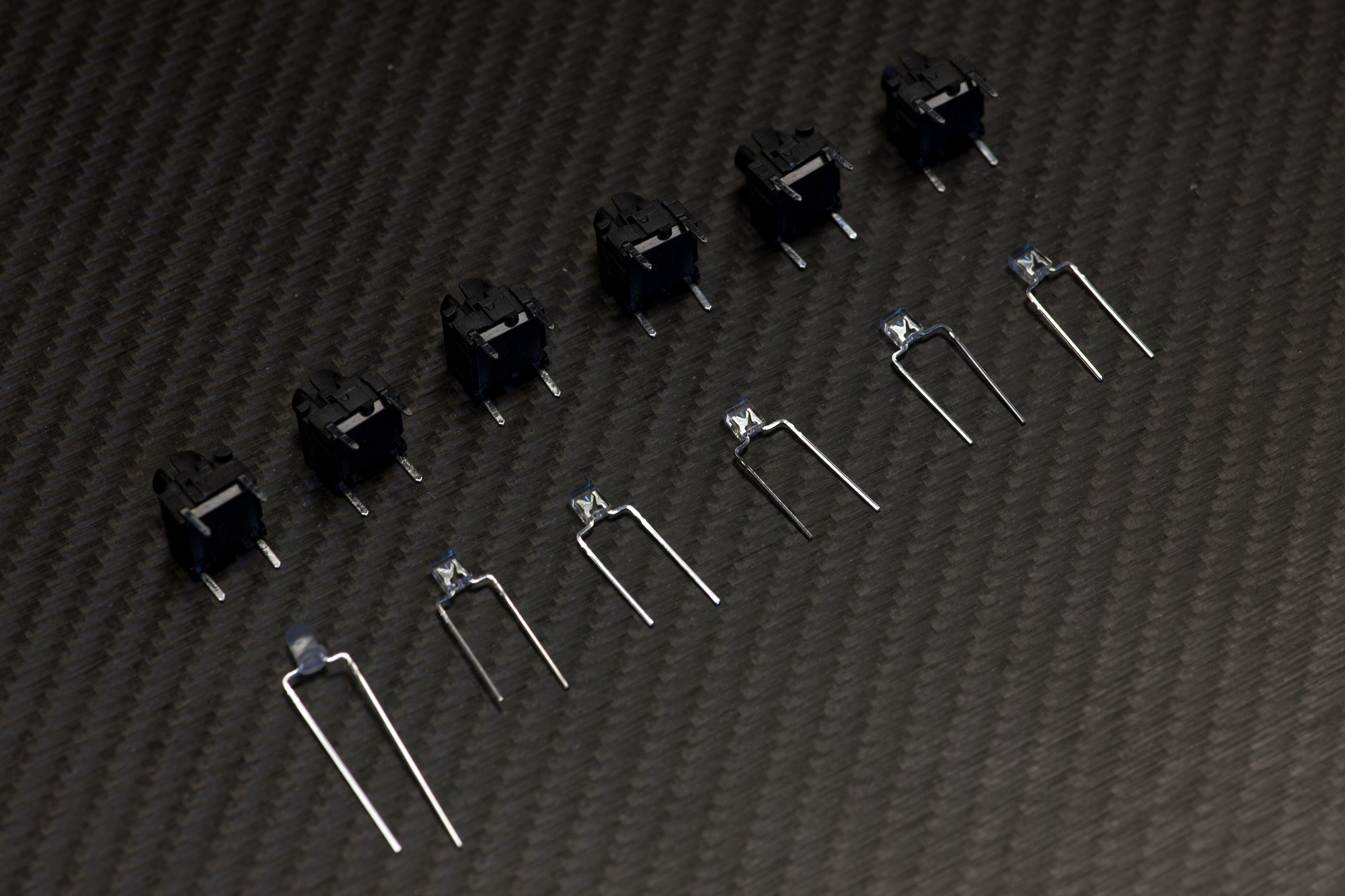
Bend MEC switch LEDs as shown
Using pincers, bend the LED legs as shown. Note the location of the longer legs (LED anodes).
You will need to bend 5pcs of the 2x3x4mm white LEDs and 1 piece of the 3mm round nonpolar (bicolor) LED.
Be careful when bending the nonpolar LED legs, as these legs can break quickly if bent too often, but you will find a spare nonpolar LED in your MatriX LED kit.
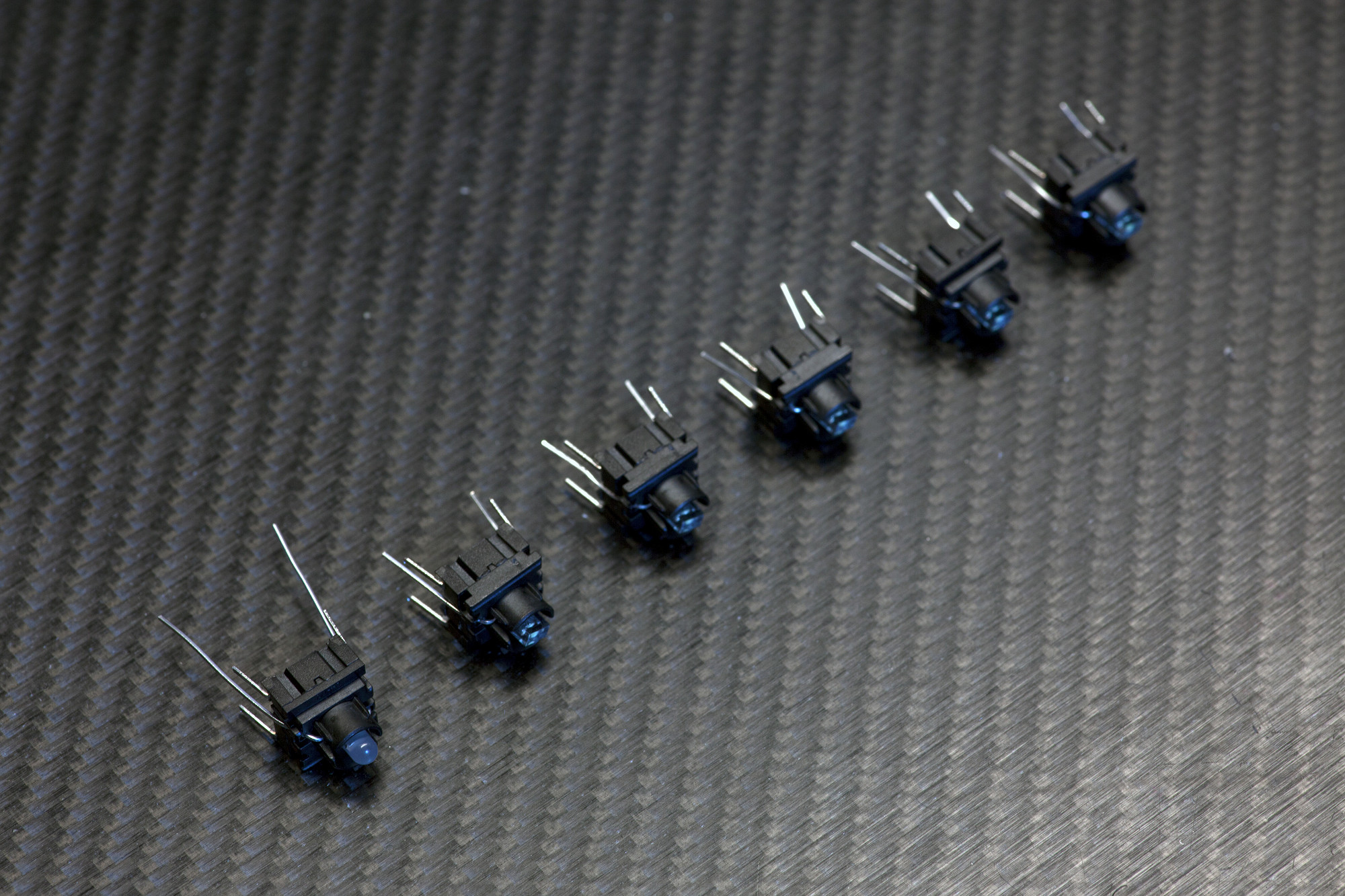
2.10 MEC SWITCH LED ASSEMBLY
Pre-install LEDs in MEC switches
Insert the nonpolar LED (leftmost MEC assembly in the picture) and the five 2x3x4mm standard white LEDs in the MEC switches as shown.
After insertion, make sure the MEC switch top can be pushed downwards (resulting in a "click") without any obstruction of the LED. Sometimes an LED leg can "block" the switch action, if this is the case, the problem is easily corrected by using pincers to bend the LED head within the MEC switch until the obstruction is removed.
Make sure the LEDs sit flush and centered and at the bottom of the MEC switch as shown in the picture.
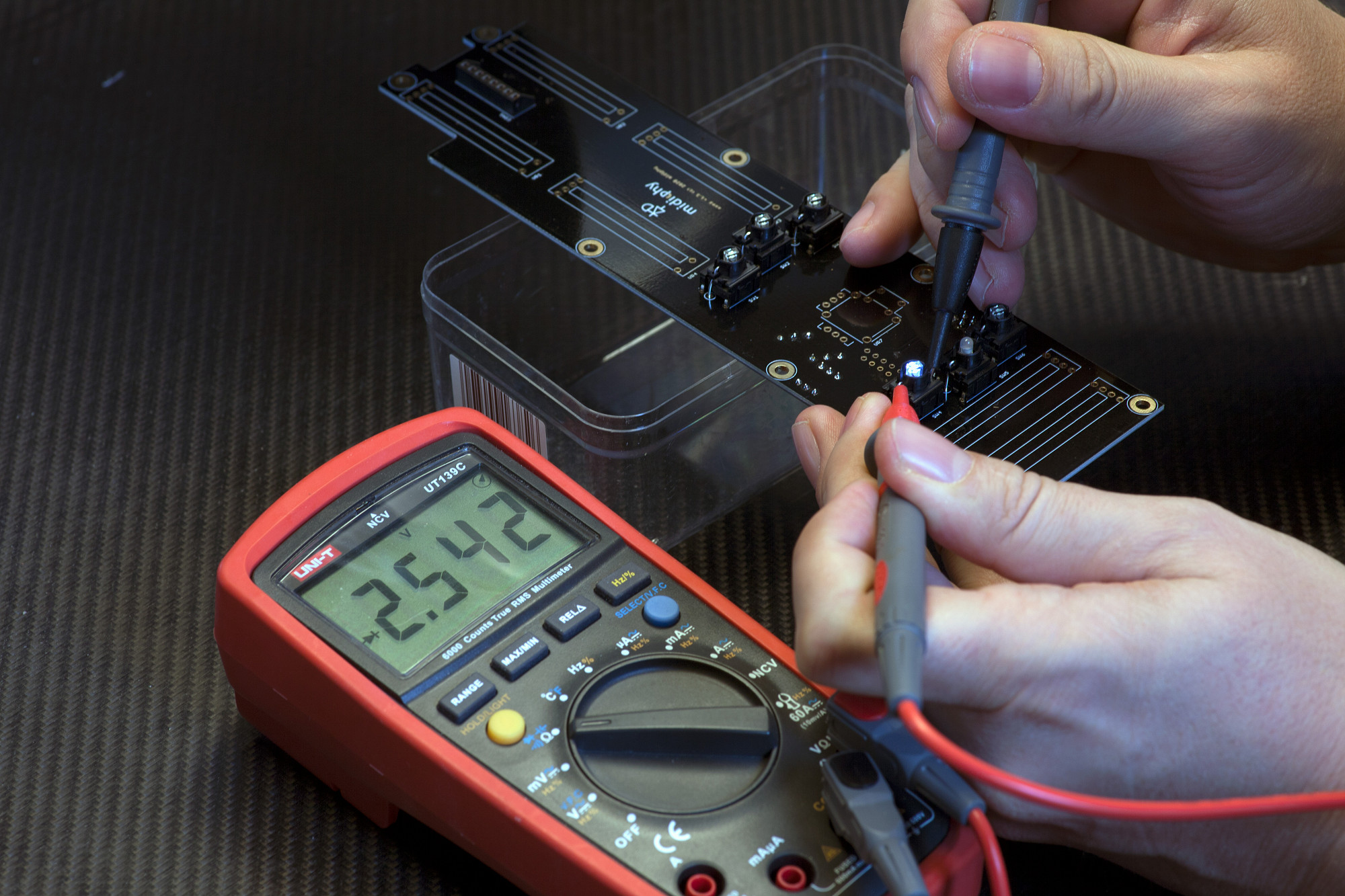
2.11 MEC LED TESTS AND SWITCH INSTALLATION
Before soldering, check LED polarity of SW1-4, SW6 LEDs, then firmly click in SW1-SW6 and solder them
Observe polarity before inserting the MEC switches: all longer LED legs go into "round" marked holes
After you've inserted the MEC switches, use a digital multimeter in diode test mode to make sure the polarity is right. As shown in this picture, hold the red probe towards the longer leg of the LED (left side on the PCB and MEC switch) and the black probe towards the shorter leg of the LED. The LED needs to light up as shown in the picture.
Make sure to install the nonpolar LED/MEC assembly in SW5, also inserting the longer LED leg into the round-marked hole.
Once you've double-checked SW1-4 and SW6 using the multimeter, make sure that all MEC switches they are sitting at an exact 90° angle to the PCB, pressed flat to the PCB, then turn over the PCB and solder them. If required, you can "tack" a single pin of the MEC assembly first, then solder all pins while pushing the MEC switch downwards with your hands - this is recommended as it ensures best "flat" contact of the switch with the PCB surface.
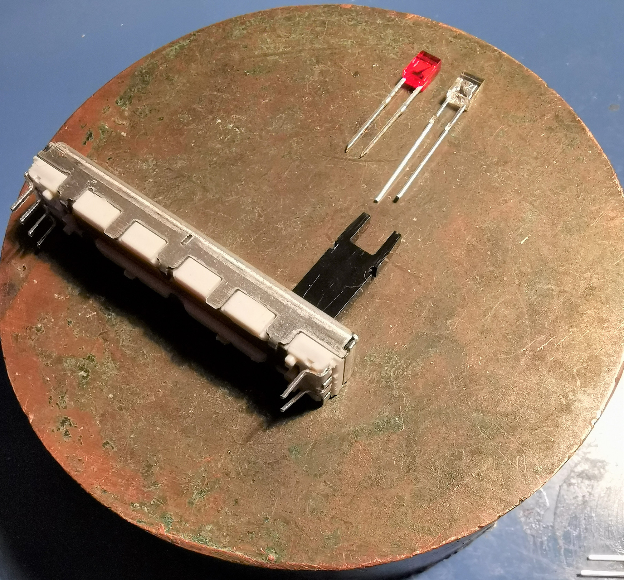
2.12 REFIT SLIDER/POTENTIOMETER LEDS WITH WHITE LEDS
Shorten 2x3x4mm LED legs and insert into sliders/potentiometers
Pull out the red (or non-white) LEDs from the sliders and use them as a reference to cut the provided 2x3x4mm white LEDs in the MatriX LED kit to length. Then insert them again - if the LEDs are not lighting up after powering up your MatriX later on, just turn them around to correct the polarity.
The LED anode side (longer legs before cutting) is oriented towards the side of the slider pot that has four pins.
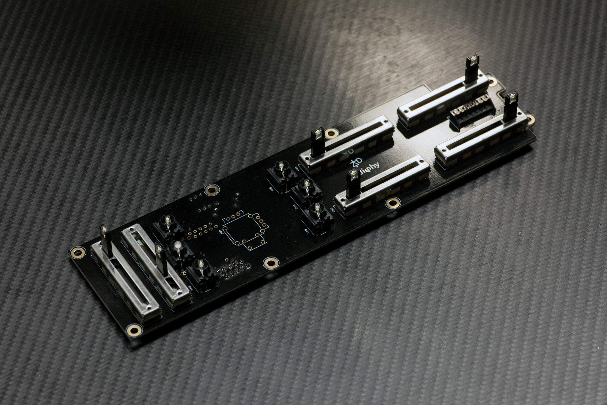
2.13 SLIDERS/POTENTIOMETERS
Solder VR1-VR6
Insert the sliders, "tack"/solder a single pin first, then make sure it sits flat on the PCB and is at an exact upright angle. Correct the alignment if necessary, then solder the remaining pins.
Solder VR1-VR6
Insert the sliders, "tack"/solder a single pin first, then make sure it sits flat on the PCB and is at an exact upright angle. Correct the alignment if necessary, then solder the remaining pins.
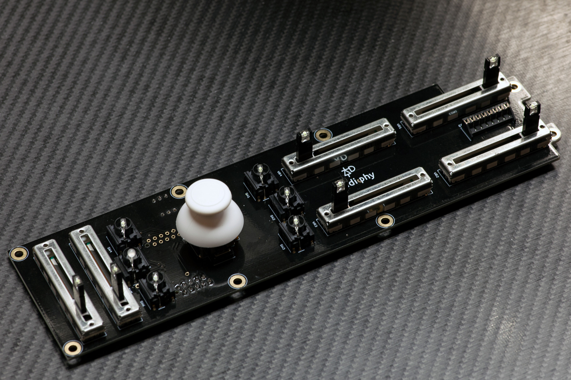
2.14 JOYSTICK and MEC SWITCH CAPS
Solder the joystick
Finally, insert the joystick. First make sure that it sits completely flat on the PCB - "tack" it by soldering two pins that are distant from each other.
Then install the joystick cap and visually check that the joystick centering results in a visually centered cap.
If the joystick cap seems to be slightly slanted either north/south or east/west after centering, you can correct this by heating up one of the two pins and slightly "lift" the joystick up on the opposing north/east/south/west side to correct it, only a fraction of a millimeter of lift will help a lot in case you were unhappy with the cap centering.
This is an optional step and is only necessary, if the centering visually seems to be not perfect when the joystick case sits flat on the PCB. Once you're satisfied, solder all pins.
You can now also install the MEC switch caps by firmly pressing them on the MEC switches (not shown in this picture).
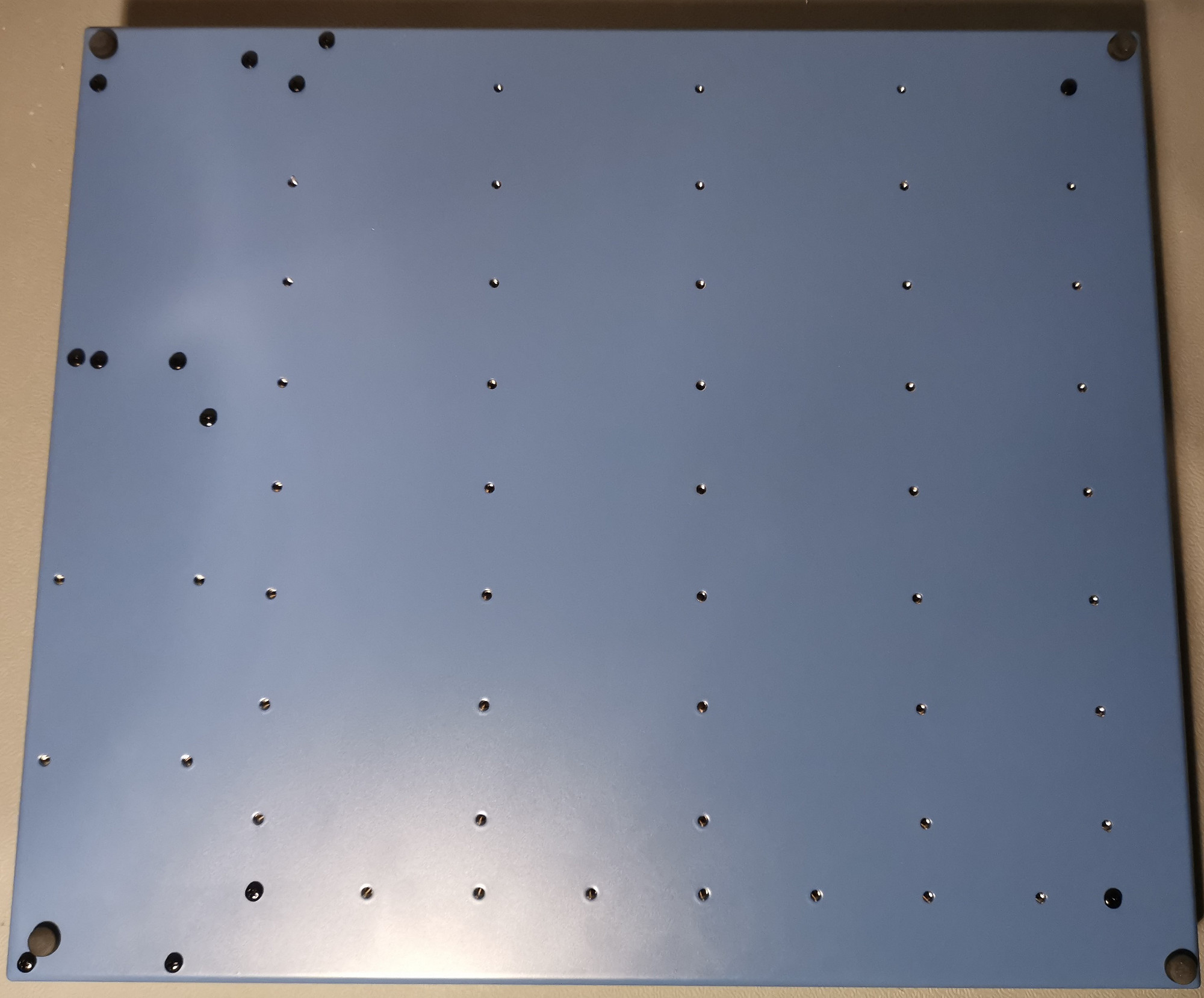
2.15 Install Axes PCB Case Standoffs
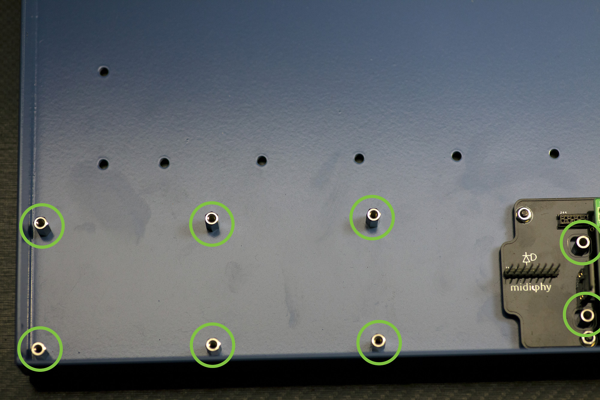
Install eight 10mm M3 standoffs in shown locations
Although we can't install the Axes PCB in the case yet, we can prepare for its installation:
Use eight black M3 screws (from the bottom of the case) to fasten eight 10mm M3 hex standoffs in the locations shown. Note that two standoffs go "through" the Core PCB.
Chapter 3: Neo PCBs
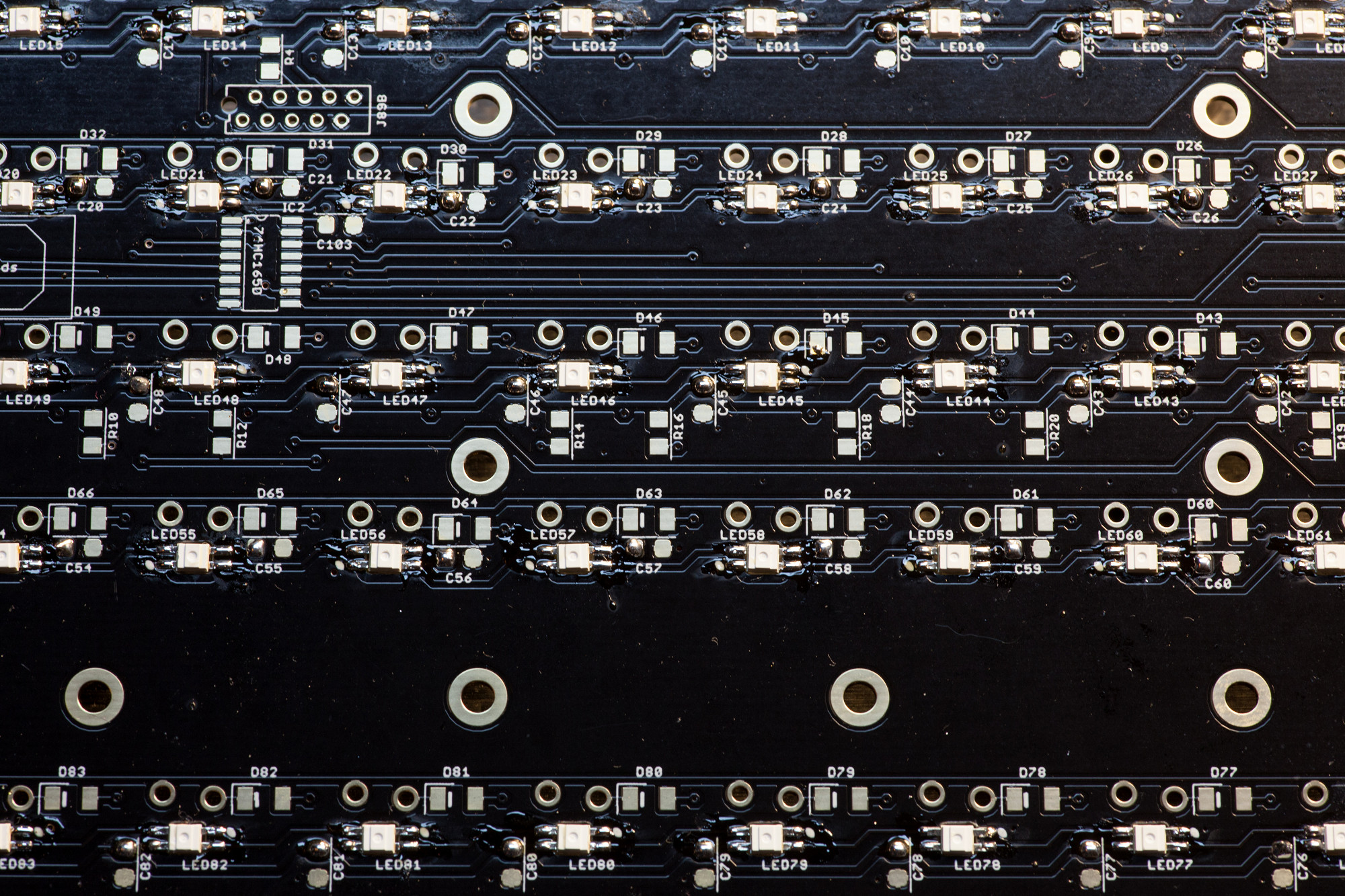
3.1 EPIXELS
Solder LEDs observing alignment @300°C.
After breaking the vacuum seal of the midiphy ePixel package, solder within two weeks.
Note that LED orientation changes for each row!
Align the 45° corner pin edge with the round dot/marks on the PCB silkscreen. To solder ePixels, make sure your soldering iron first heats up the pads on the PCB and is set to 300°C only. Then flow a bit of solder onto the heated pad until the ePixel "sticks". Continue with the remaining three pads, until the ePixel is fully soldered (see picture). Note that overheated/burned ePixels may continue to work, but operate at a noticably reduced brightness level - these LEDs should be replaced for a uniform illumination of the keyboard.
If you ever need to remove a non-operational or "dim" ePixel, you can either use desoldering braid or better an SMT hot air reflow station to evenly heat up all pads and then remove the LED with your SMT tweezers.
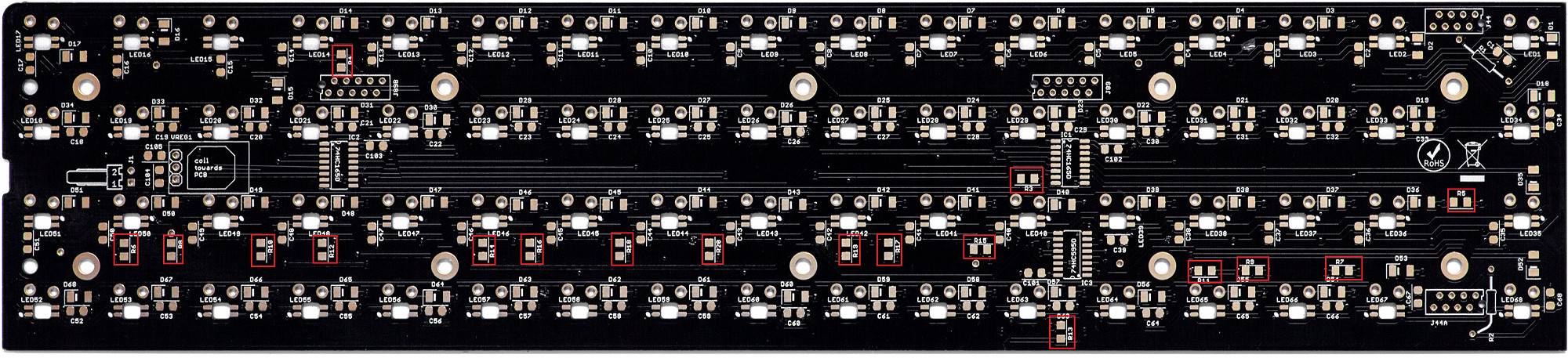
3.2 SMT Resistors
Solder SMT Resistors
Each board has a total of 18x 10k 1206 resistors. It's easier to find the resistors now, then the remaining 1206 components will all be 100nF capacitors. Count that exactly18 parts are soldered in per board.
For the neo_85 board, the resistors are in approximately the same positions, except R13 has a horizontal orientation and R5 is located to the right of LED67.
3.3 SMT Signal Diodes and BAT54S Diodes
Solder SMT diodes, observing their alignment.
Next up, tin one side of the SMT diodes, then use your SMT tweezers to hold them in place and solder them. Afterwards, rotate the PCB by 180° and solder the other pins.
BAT54S diodes near the J44/J89 connectors should normally not be required, but if the digital behavior is strange you can try to solder a diode in or simply bridge the three pads with a wire/solder blob. As an explanation: all 0V lines are "star-wired" back to the DC input and 0V is not connected between neo boards. An antiparallel Schottky would keep the 0V of different domains within a diode drop.
3.4 SMT Capacitors
Solder 100n SMT capacitors
Solder all SMT capacitors next - the capacitors close to the ePixels are 100nF. Capacitors near the voltage regulator are typically not required.
Ignore the silkscreen marking for the voltage regulator, that's the old version.
Solder 100n SMT capacitors
Solder all SMT capacitors next - the capacitors close to the ePixels are 100nF. Capacitors near the voltage regulator are typically not required.
Ignore the silkscreen marking for the voltage regulator, that's the old version.
3.5 SMT ICs
Solder SMT ICs, observing alignment
Just as with the other PCBs, first tack the ICs by soldering two pins on one side, then drag-solder the other side, then drag-solder the original side. Always check the SMT IC pins with a loupe/magnifying glass for unwanted shorts and also that every pin has proper contact with its PCB pad.
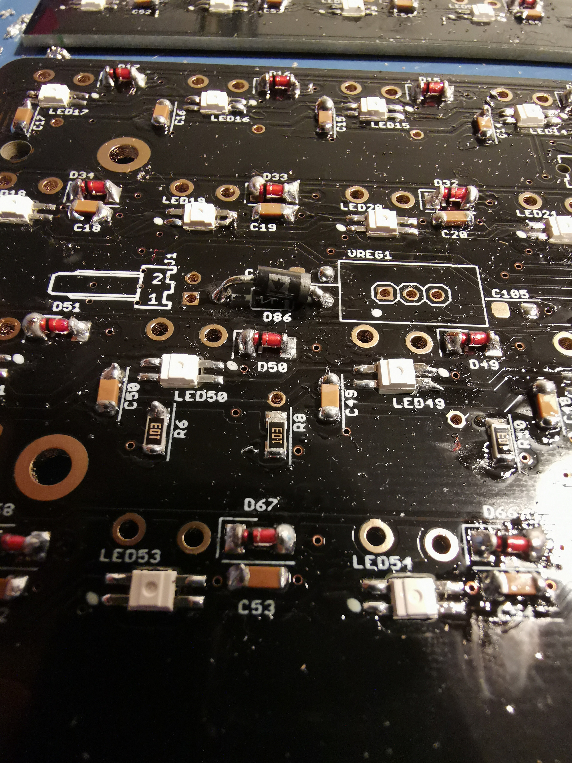
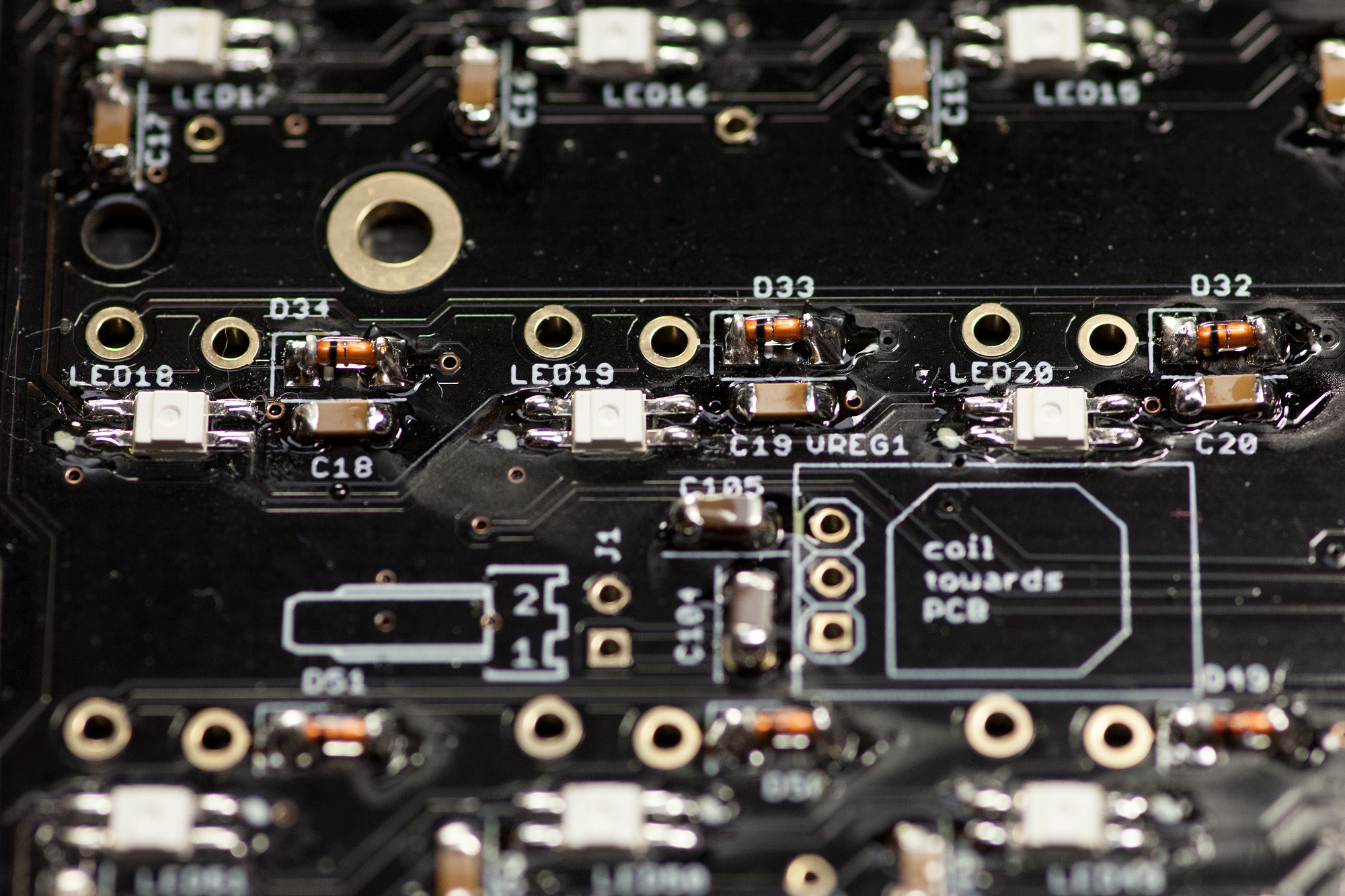
3.6 THT Resistors and Diodes
Top-solder THT Resistors, cutting pins flush to the PCB
Do the same for the Schottky diode located between the Molex header and voltage regulator. The band should be oriented according to the silkscreen (closer to the regulator).
Top-solder THT Resistors, cutting pins flush to the PCB
Do the same for the Schottky diode located between the Molex header and voltage regulator. The band should be oriented according to the silkscreen (closer to the regulator).
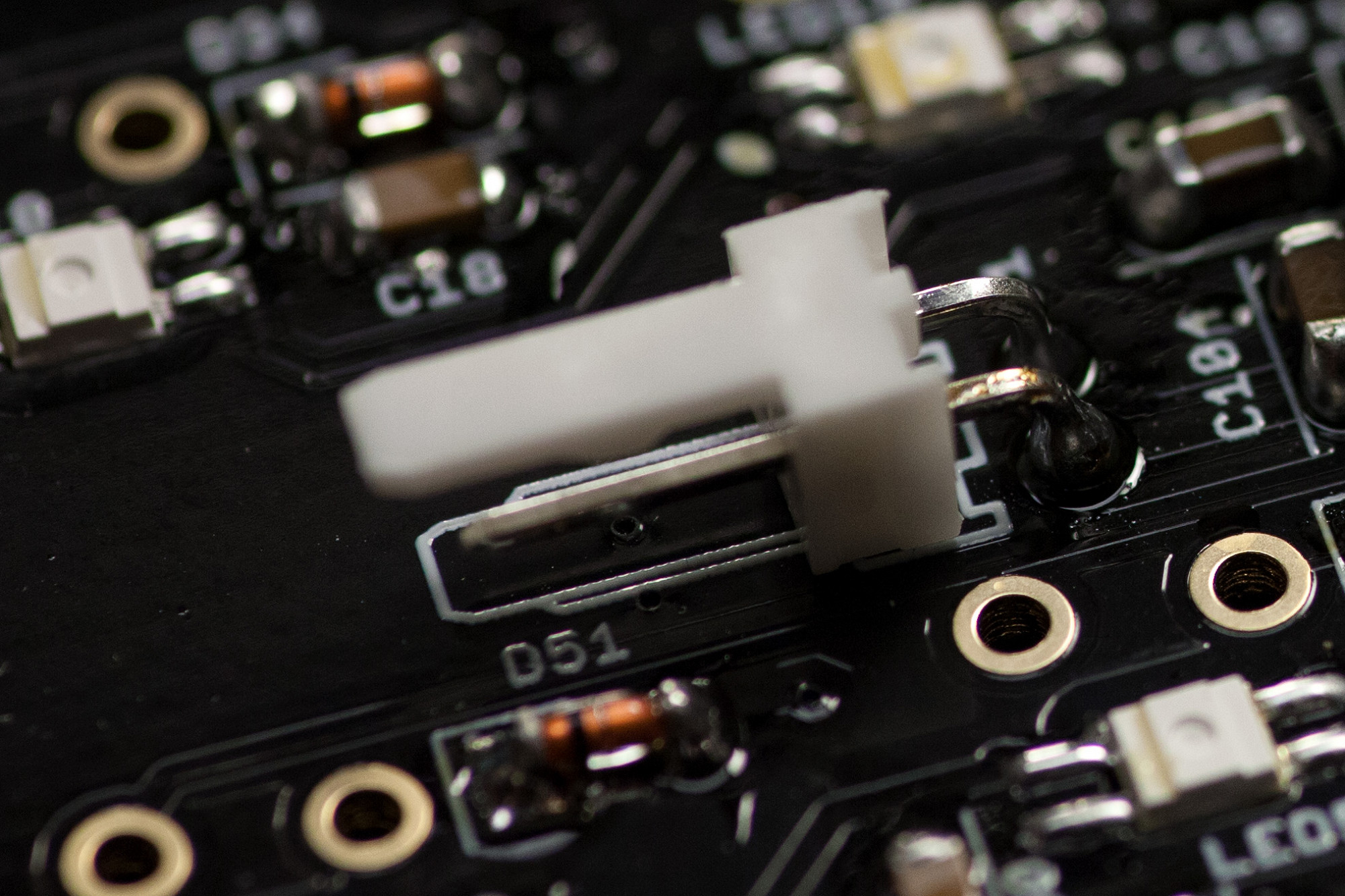
3.7 Molex Power Connector
Check for correct alignment before soldering
Align the connector with the silkscreen, turn over the PCB and solder it. You can trim the pins on the solder side, but it is usually not necessary, as there will be 3mm of spacing to the metal switch tray.
Check for correct alignment before soldering
Align the connector with the silkscreen, turn over the PCB and solder it. You can trim the pins on the solder side, but it is usually not necessary, as there will be 3mm of spacing to the metal switch tray.
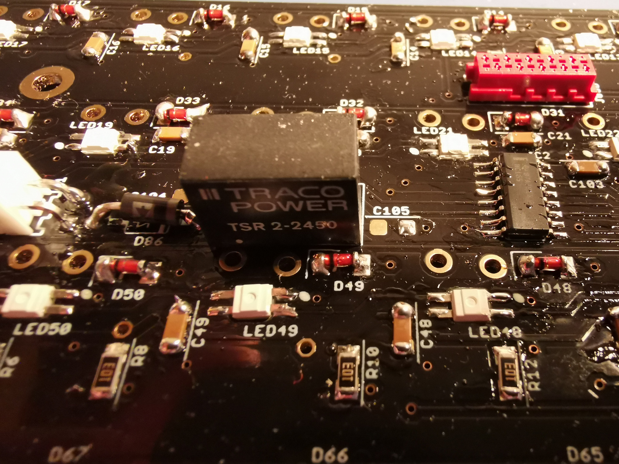
3.8 Switching Voltage Regulator
Install VREG1
Trim the pins after soldering.
Install VREG1
Trim the pins after soldering.
3.9 Micromatch Connectors
Solder micromatch connectors
Each neo PCB has four micromatch connectors (two eight-pin and two ten-pin connectors). Click them in, then turn over the PCB and solder them. If the connectors only have one notch, ensure that this aligns with the hole in the PCB.
3.10 Clean flux residues (optional)
Using alcohol or similar, clean any residues off the front of the board
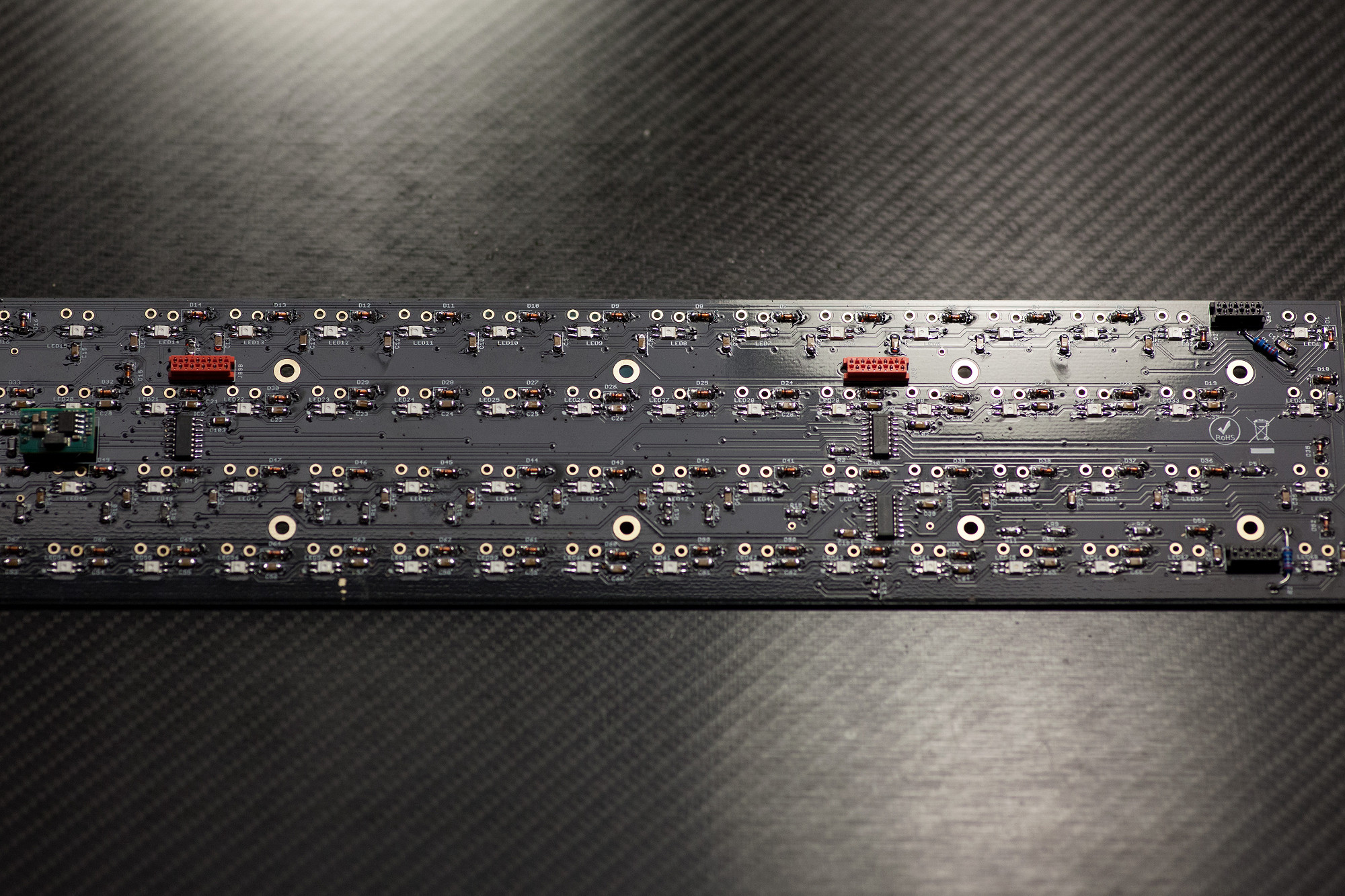
3.11 Check over the boards
Perform a visual check of soldering
Any pads or components unsoldered or missing?
Solder bridges?
Shorts across the power rails? Use a multimeter to test.
3.12 Check LED orientation
From the front of the boards, check to see if all LED corner notches align across the row
The orientation changes between rows.
LEDs powered on with reversed polarity will be damaged!
Solder micromatch connectors
Each neo PCB has four micromatch connectors (two eight-pin and two ten-pin connectors). Click them in, then turn over the PCB and solder them. If the connectors only have one notch, ensure that this aligns with the hole in the PCB.
3.10 Clean flux residues (optional)
Using alcohol or similar, clean any residues off the front of the board
3.11 Check over the boards
Perform a visual check of soldering
Any pads or components unsoldered or missing?
Solder bridges?
Shorts across the power rails? Use a multimeter to test.
3.12 Check LED orientation
From the front of the boards, check to see if all LED corner notches align across the row
The orientation changes between rows.
LEDs powered on with reversed polarity will be damaged!
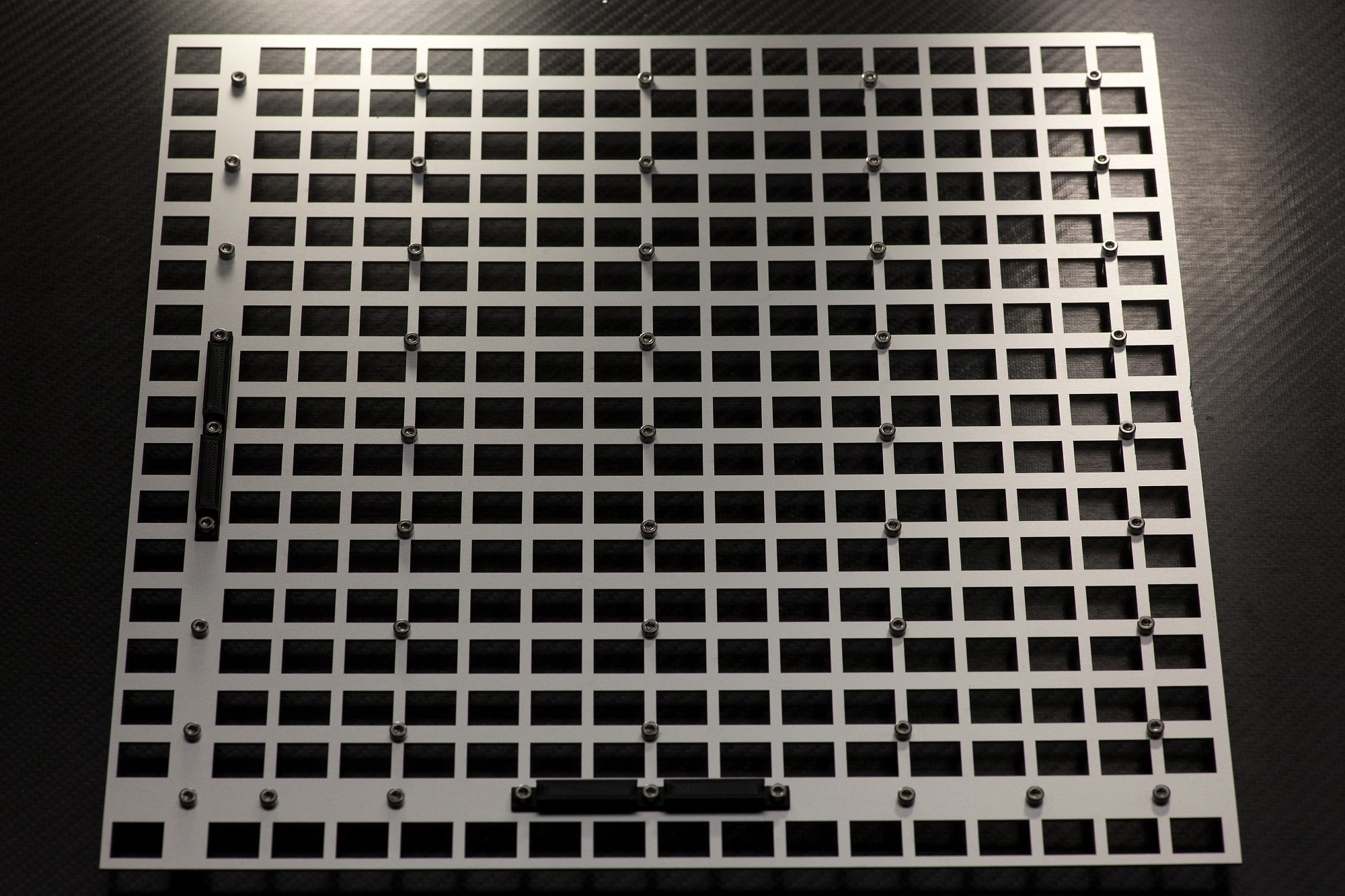
3.13 Switch Plate Preparation
Install M3x12 screws
Set the two plastic spacer parts in locations as shown and drop the M3 Allen head screws in all holes.
Install M3x12 screws
Set the two plastic spacer parts in locations as shown and drop the M3 Allen head screws in all holes.
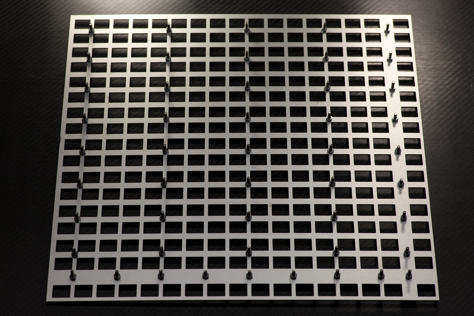
3.14 Install 3mm spacing nuts
Fasten M3 Allen head screws
Fasten the M3 screws with M3 nuts on the back. These serve as spacers between the plate and the neo PCBs. If you have trouble mounting neo boards, you could consider to loosen some of these screws before tightening again.
Fasten M3 Allen head screws
Fasten the M3 screws with M3 nuts on the back. These serve as spacers between the plate and the neo PCBs. If you have trouble mounting neo boards, you could consider to loosen some of these screws before tightening again.
3.15 Neo PCB Fastening
Tightly fasten spacing nuts and secure neo PCBs on plate
Install onto the switch plate. After you've added a new neo PCB, push it down from the top while screwing in the M3 Allen head screws from the bottom to firmly secure the M3 spacing nuts to the plate first.
Double check that all allen screw heads sit flush on the metal plate front surface and that all M3 spacing nuts are firmly fastened to the metal plate backside, now without any wiggle room. All neo PCBs are then spaced 3mm away from the metal plate - this is necessary for uniform switch installation.
After that, fasten the Neo PCBs with 14mm M3 hex spacers as shown in the picture.
Chapter 4: Building the Power Cable Harness
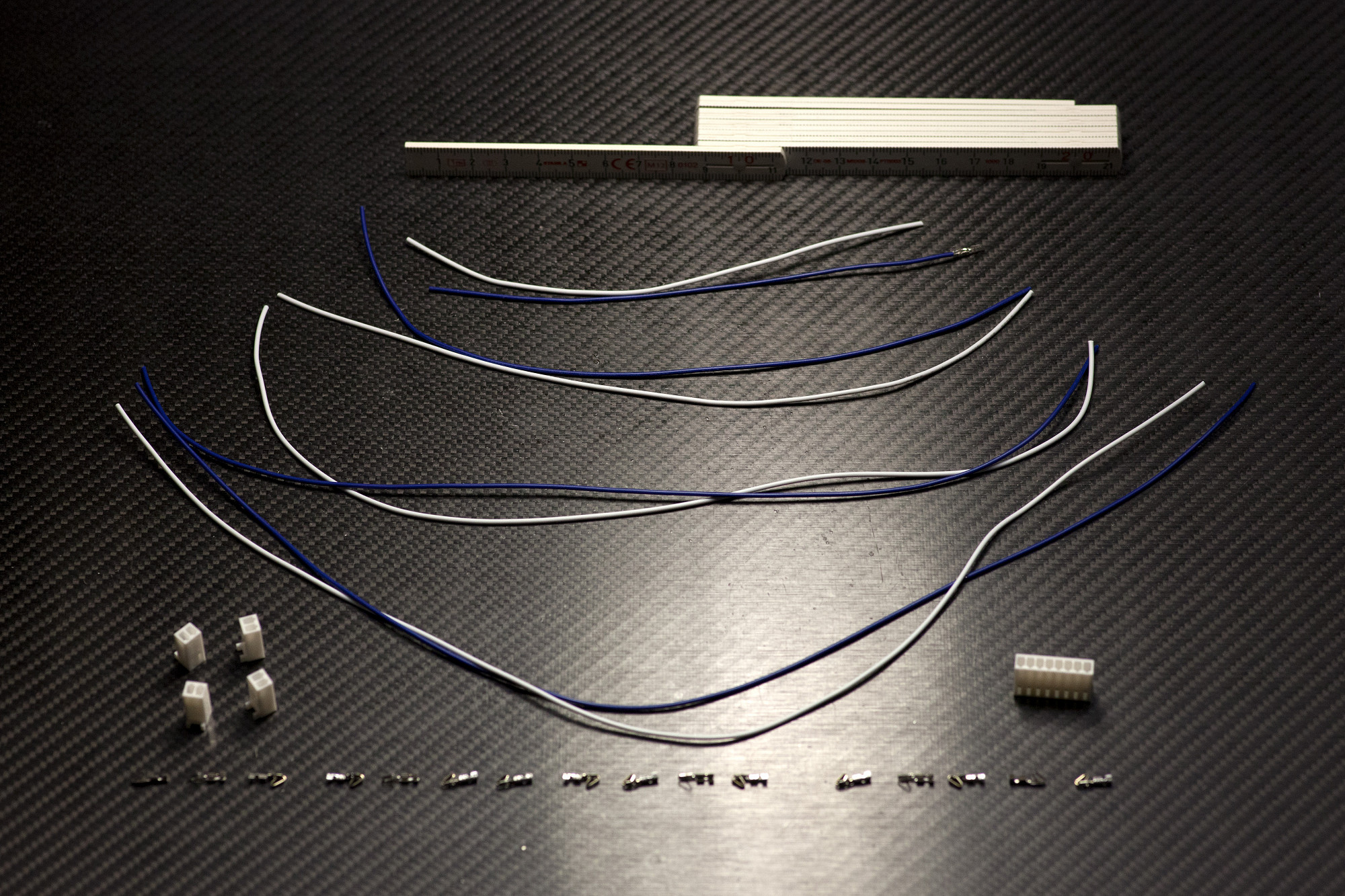
4.1 Prepare Power Harness Parts
Cut wires and Molex crimp headers
Cut four different-color wire pairs with lengths of 16/24/32/40 cm each for a total of eight wires.
If your Molex crimp headers were delivered on a spool, also prepare them by cutting them close to their terminals with your side cutters. You will need 16 of them for the power harness.
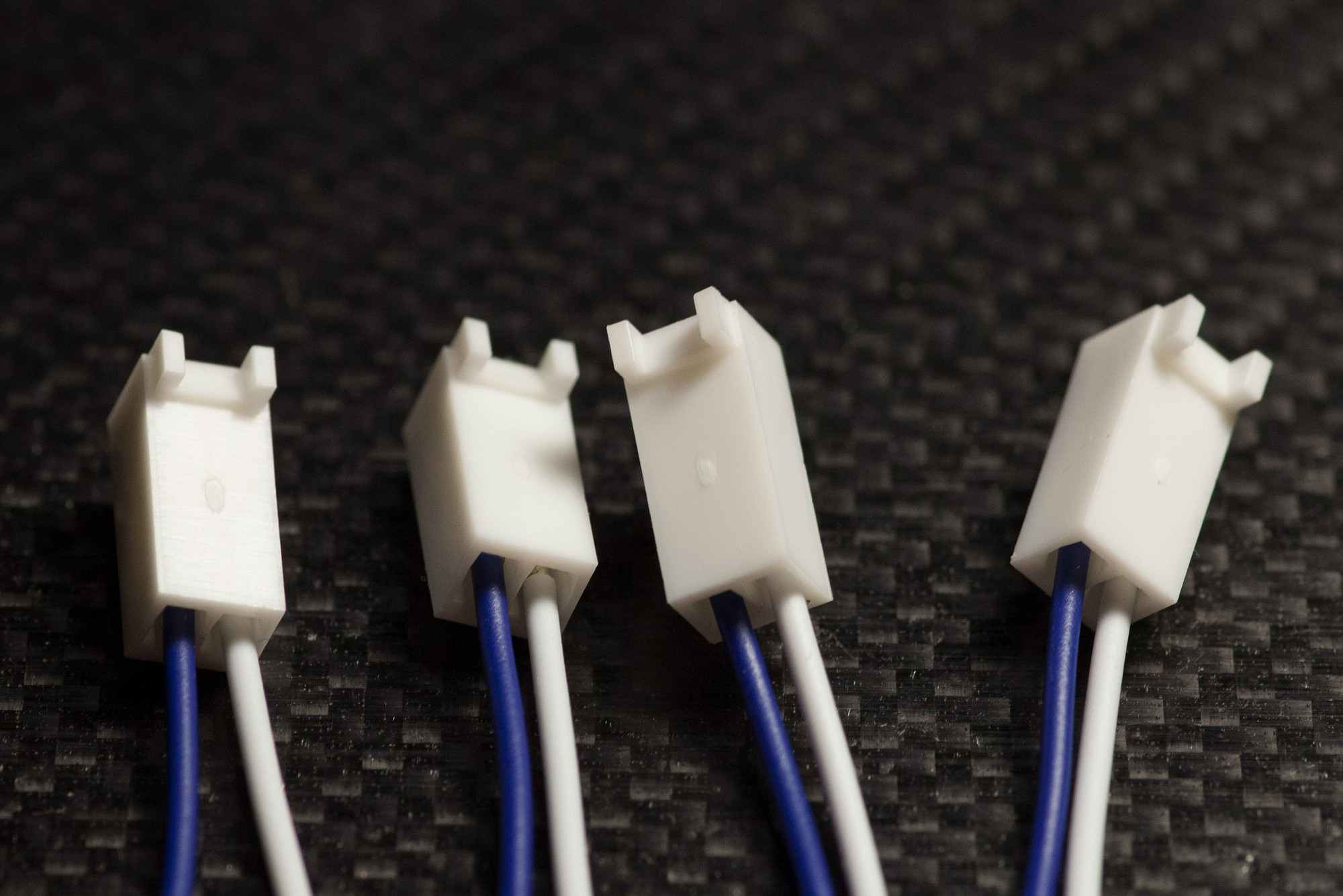
4.2 Build Neo Connectors
Crimp the neo PCB side of the power supply Molex connectors
Crimp the Molex connectors on one side of the wires first, then "click" pairs of equal cable length into the 2-pin Molex housings as shown, observing the polarity and color order of the wires.
Crimp the neo PCB side of the power supply Molex connectors
Crimp the Molex connectors on one side of the wires first, then "click" pairs of equal cable length into the 2-pin Molex housings as shown, observing the polarity and color order of the wires.
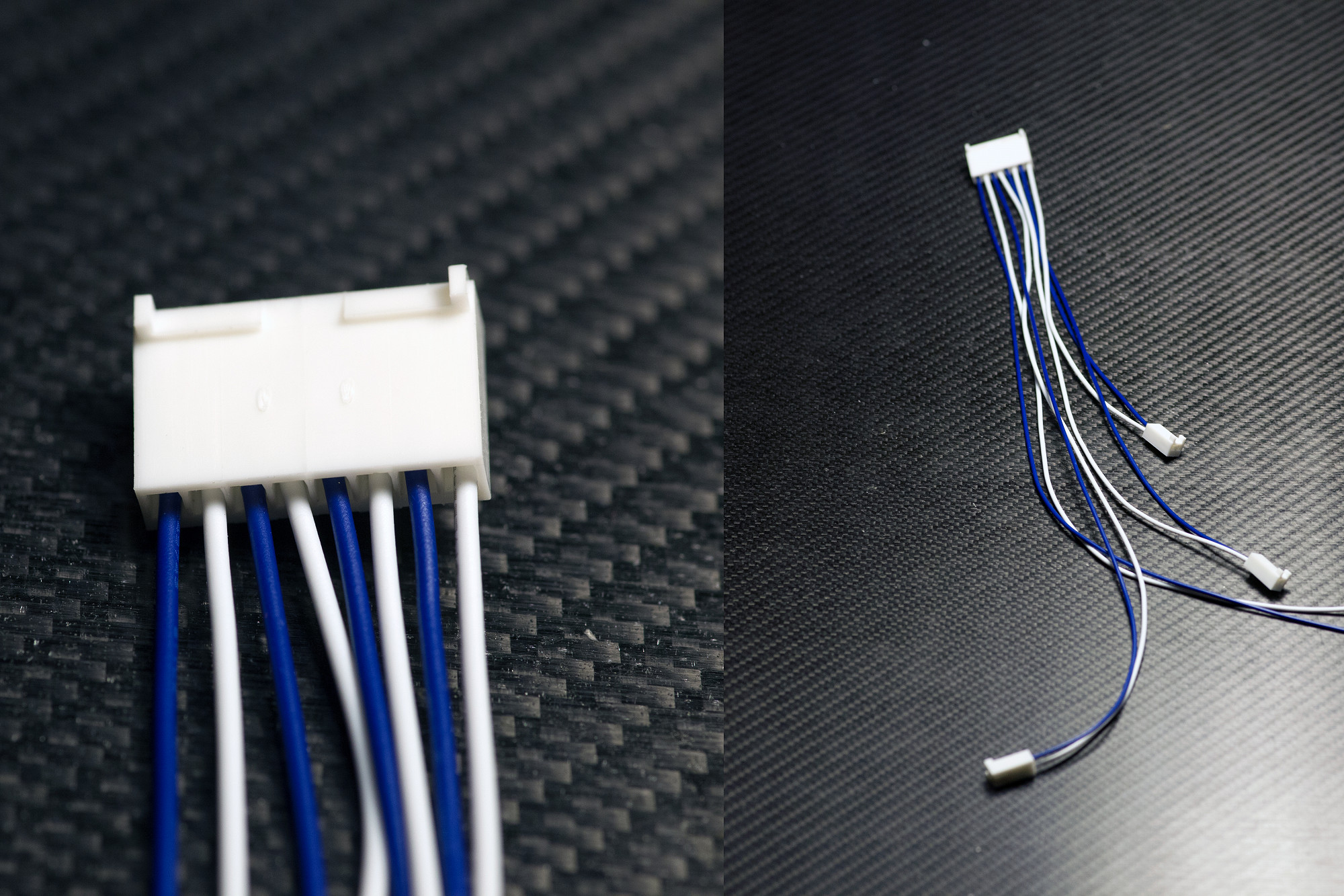
4.3 Build Core Connector
Crimp the core PCB side of the power supply Molex connectors
Crimp the Molex connectors on one side of the wires first, then "click" pairs of equal cable length into the 8-pin Molex housing as shown, observing the polarity and color order of the wires.
Crimp the core PCB side of the power supply Molex connectors
Crimp the Molex connectors on one side of the wires first, then "click" pairs of equal cable length into the 8-pin Molex housing as shown, observing the polarity and color order of the wires.
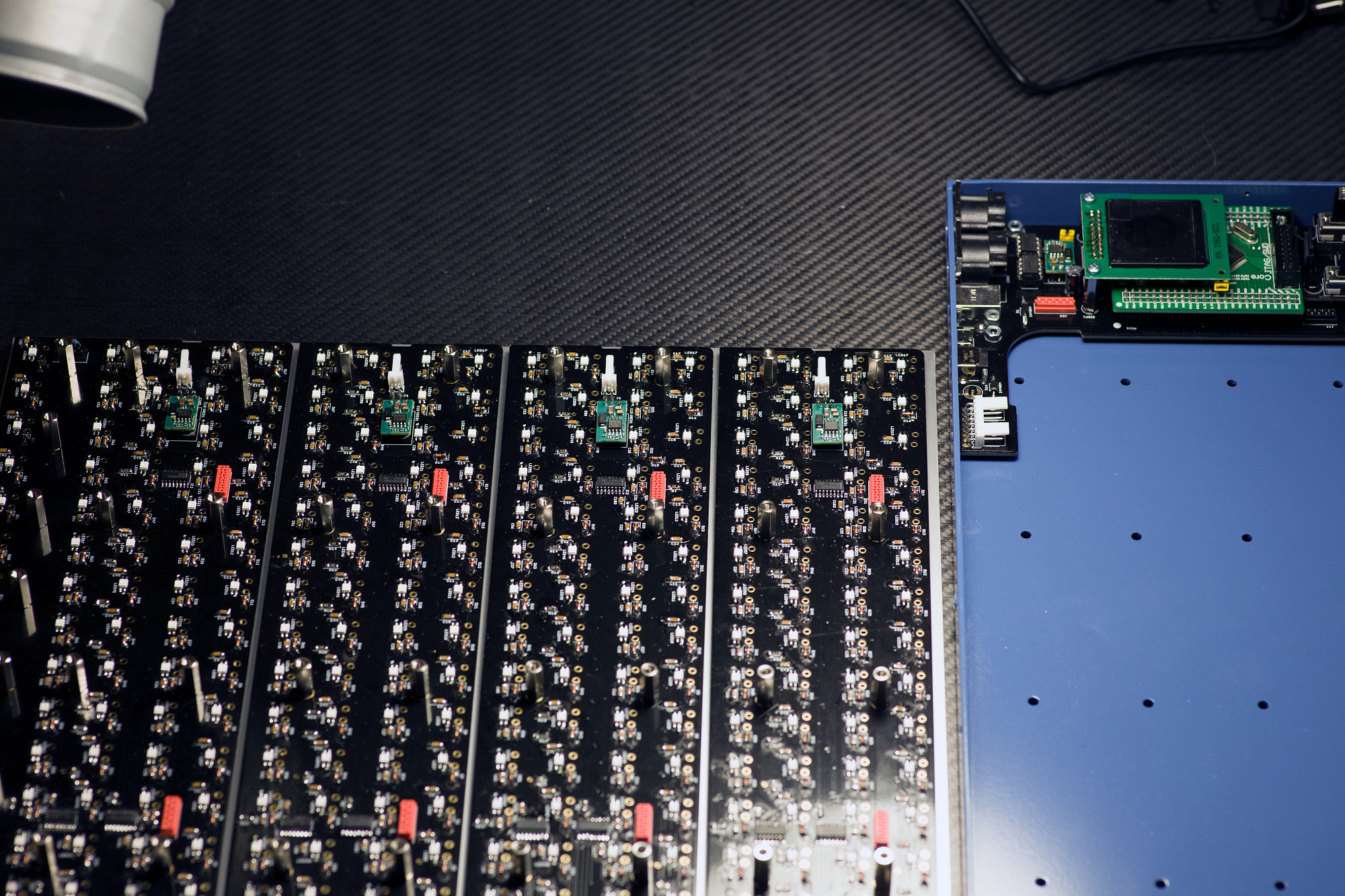
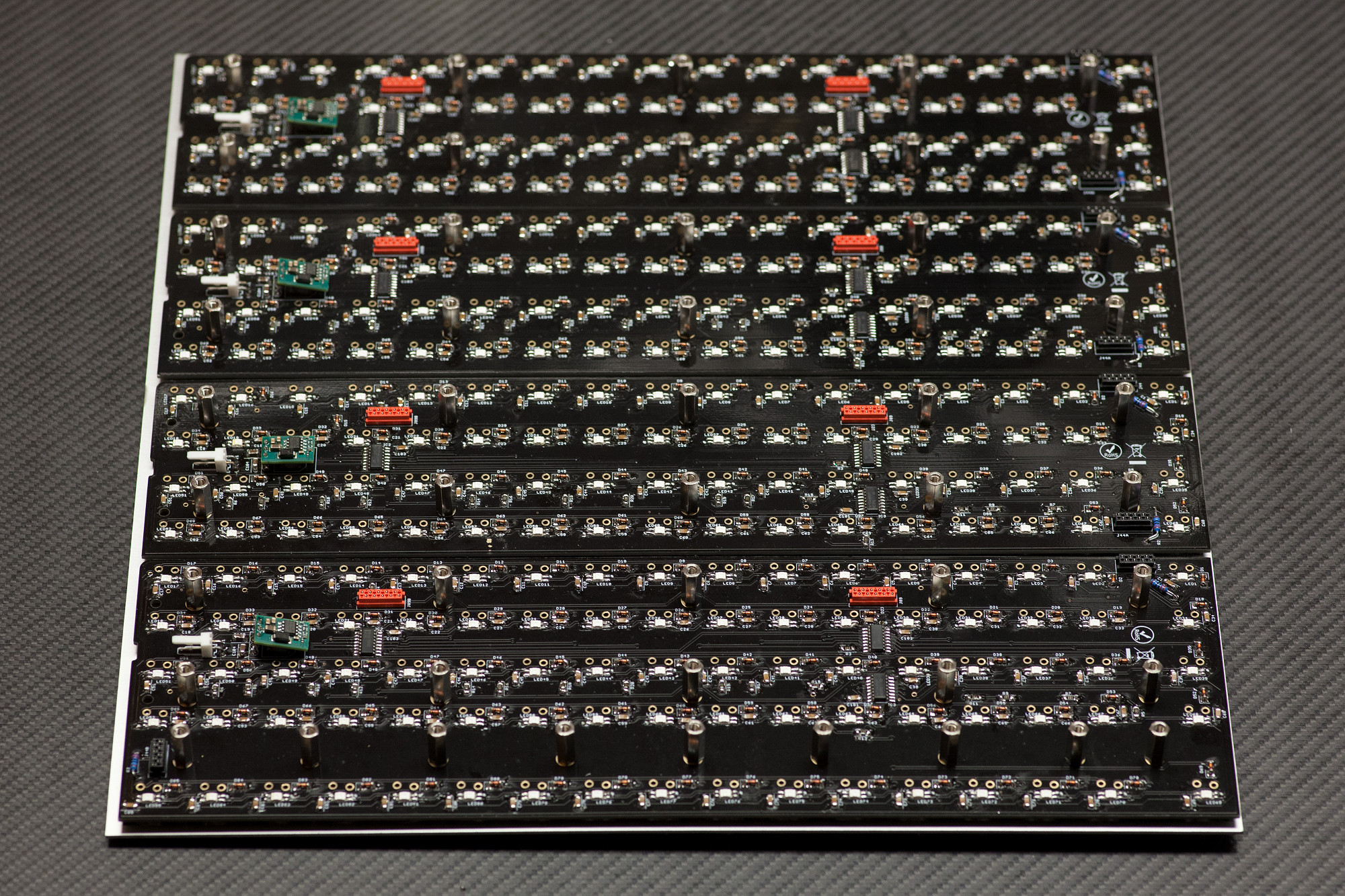
4.4 Neo-Plate Assembly Installation
Prepare your work area - place the assembly next to MatriX case
Place the assembly of neo boards next to the MatriX case as shown in the picture - in an orientation like this, all cables and wires can be installed while the assembly lies flat on your workbench - when everything is cabled, the neo-plate can be "flipped over" 180° and is ready to be installed in the case.
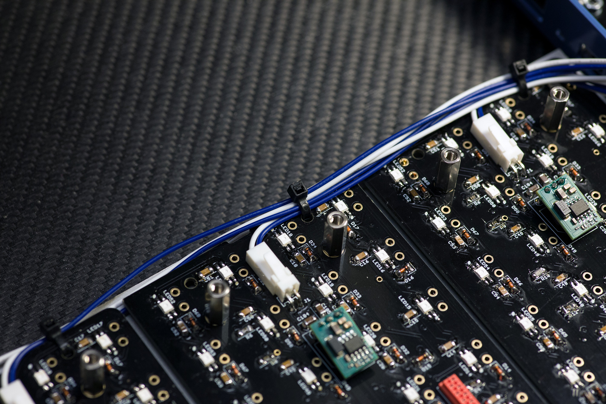
4.5 Power harness fastening
Use zip ties to fasten the power harness
The neo boards have holes for fastening the power harness - "bundle" all wires as shown and use zip ties for proper fastening of the harness.
Check that you can easily plug in the 8-pin Molex power header on the core PCB, but leave it disconnected for now, we're first installing all keys next.
Chapter 5: Mechanical Keyboard Installation
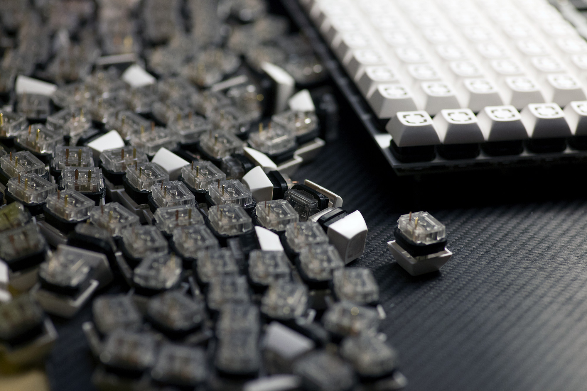
5.1 Prepare Matias keyboard switches
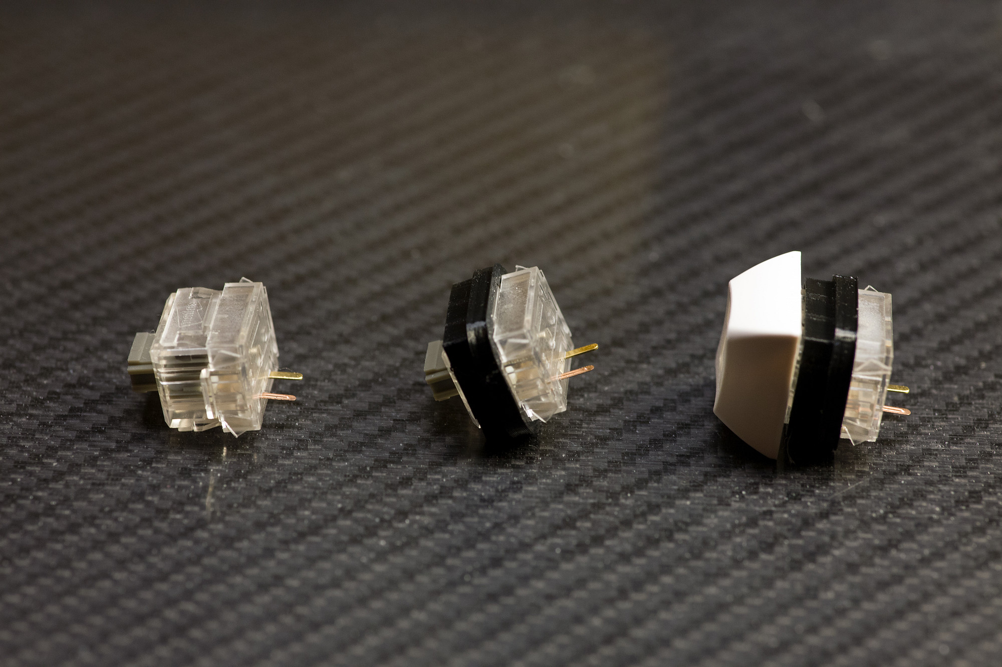
Install light|shields first, then install L4 keycaps
As shown in the picture, make sure to first click on the light|shields (they need to go "all the way down" over the small notches of the keys, as shown in the center picture) - then install the L4 keycaps on the Matias switches.
Install light|shields first, then install L4 keycaps
As shown in the picture, make sure to first click on the light|shields (they need to go "all the way down" over the small notches of the keys, as shown in the center picture) - then install the L4 keycaps on the Matias switches.
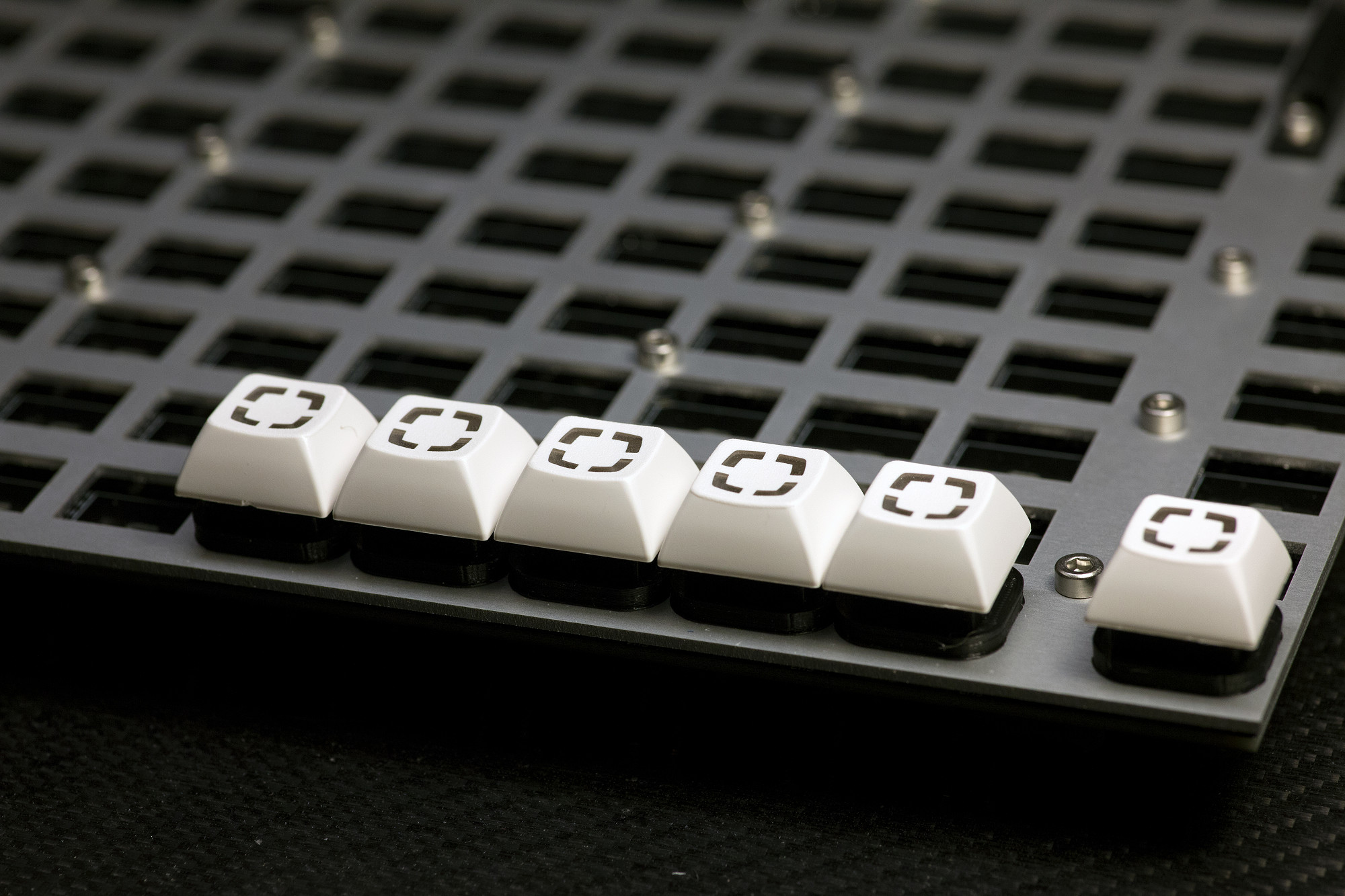
5.2 Install Keys
"Click-in" all prepared keys
Start from one corner of the tray assembly and "click in" all keys as shown. The metal tray will "grab" them tightly and stabilize them, a bit of force may be needed.
Check that all light|shields sit flush on the metal tray.
Important: After installation of each row of keys, make sure to check on the neo PCB back, that no pins were accidentally "bent" - there need to be two matias pins visible for every key location on the PCB backside, check every location!
5.3 Click... Click... Repeat
This should be good finger training... :)
This should be good finger training... :)
5.4 Solder Keyboard Switches
Solder Matias switches
After double-checking that all Matias switches sit flat on the PCBs (and both pins are visible for each switch), you can solder all switch pins.
Solder Matias switches
After double-checking that all Matias switches sit flat on the PCBs (and both pins are visible for each switch), you can solder all switch pins.
Chapter 6: Micromatch Ribbon Cables
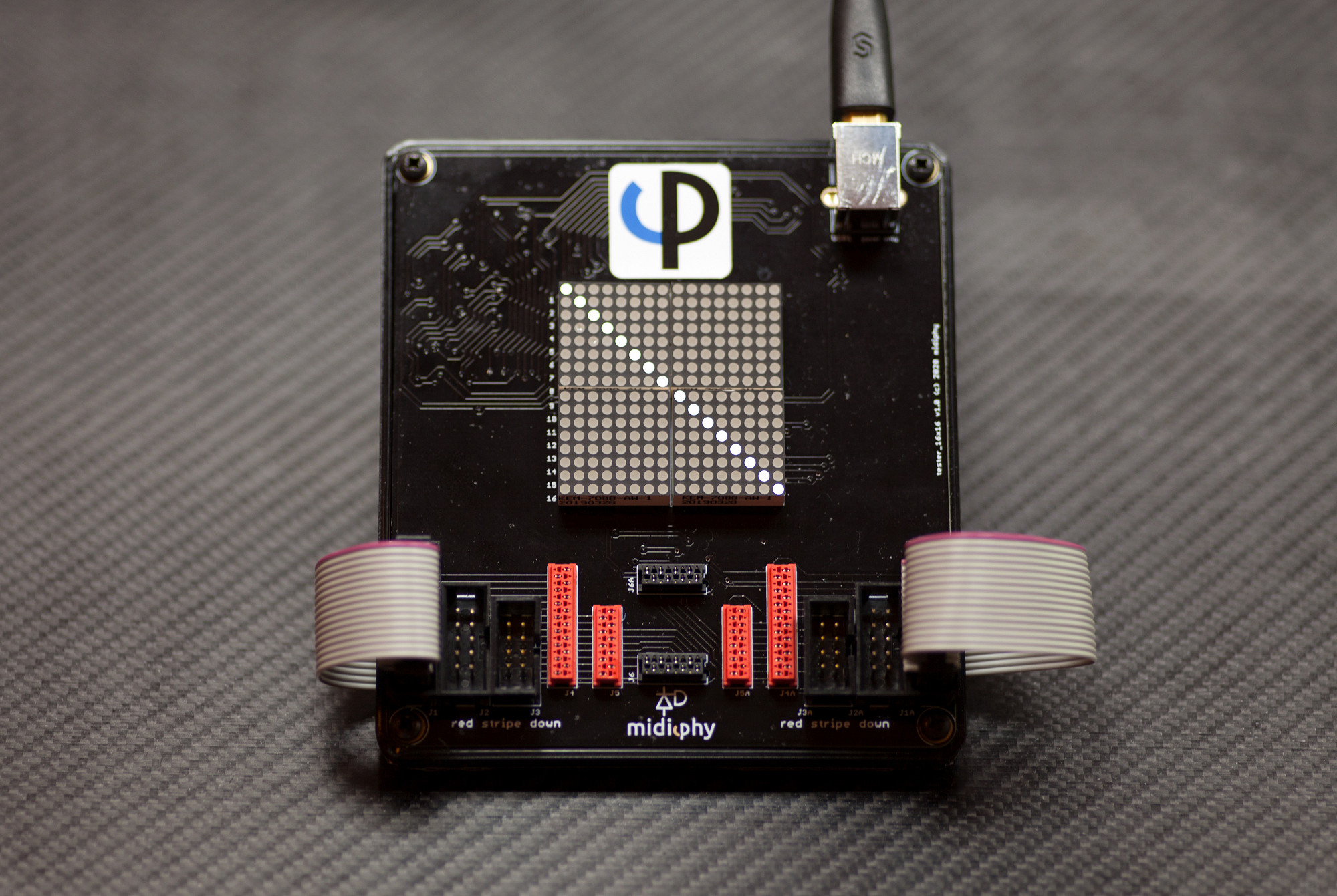
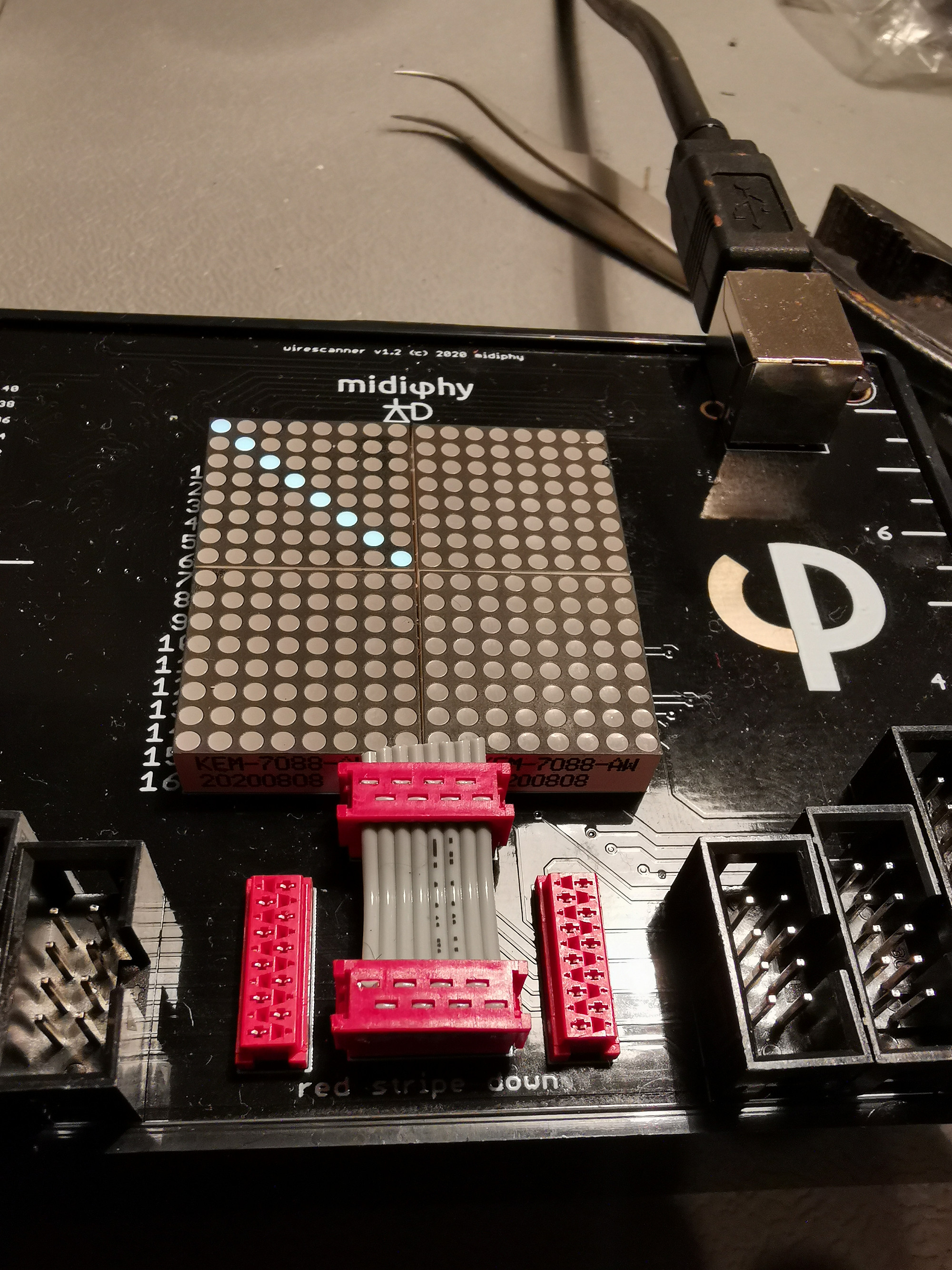
6.1 Prepare midiphy wirescanner tool
If you have not built it yet, it's highly recommended to finish your wirescanner before proceeding...
The wirescanner will allow you to check all required micromatch data cables within the MatriX - as bad cables have proven to be a major source of problems in previous DIY builds, we highly recommend to test every built cable with the wirescanner first.
All built cables should show a diagonal graph starting at the top left point) with a length of either 8 dots or 10 dots, depending on the ribbon cable width.
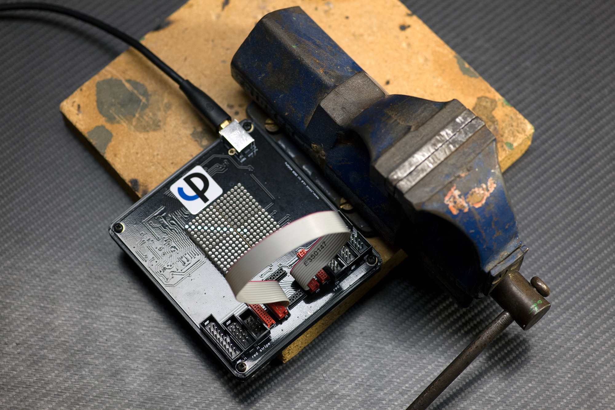
6.2 Build the Micromatch ribbon cables
To properly build a micromatch ribbon cable, use a bench vise to "hold" the micromatch connector vertically, make sure the vise does not grip the protruding polarity pin, but the rest of the connector case.
Then install the ribbon wire from the side at a 90° angle to the connector and close the bench vise until you hear 2 "clicks".
Install the other micromatch connector on the other side of the cable and make sure to align the red wire to the micromatch connector polarity pin on both sides of the cable.
After you built a cable, make sure to instantly test it using the wirescanner - the shown diagonal graph indicates a good 10-pin cable.
6.3 Build short interboard connectors
Carefully build, test and install three short interboard connectors
The easiest way to get the right spacing is to either use the wirescanner tool or assemble them directly on the neo boards mounted to the plate. The 1.65cm distance between two micromatch MOW8 connectors should perfectly match. This corresponds to about 2.5cm of ribbon cable for each.
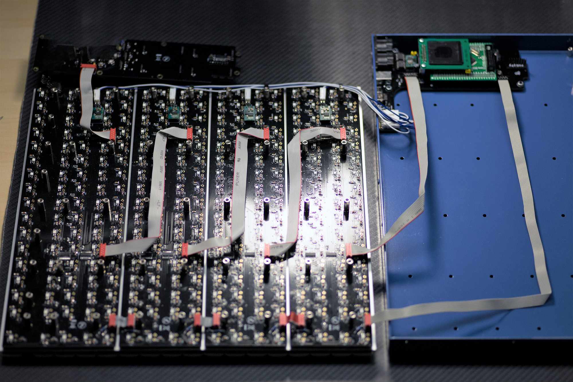
6.4 Wiring Goal
Carefully build nine micromatch ribbon wire cables and install as shown
Make sure you can "flip back" the tray assembly easily, with no ribbon wires obfuscating the 14mm hex standoffs of the tray.
Build micromatch ribbon cables of the following lengths and connect the respective PCBs:
Core J44 -> Neo1 J44 (MOW8; 47cm)
Core J89 -> Neo1 J89 (MOW10; 31cm)
Neo1 J89A -> Neo2 J89 (MOW10; 23cm bend as "Z")
Neo2 J89A -> Neo3 J89 (MOW10; 23cm bend as "Z")
Neo3 J89A -> Neo4 J89 (MOW10; 23cm bend as "Z")
Neo4 J89A -> Axes J89 (MOW10; 25cm)
----- leave the axes board disconnected for now
Connect the short MOW8 J44 interconnect cables from the previous step if not already present
7 Assembly and Testing
7.1 Power up and debug ePixel chain
For an initial test of LEDs, power up with the neo plate still sitting face down
It is easy to spot where the LED chain gets interrupted. Possible causes are:
Dead LED (remove and replace)
Inverted polarity (remove and replace; the reversed polarity probably will have killed the LED)
Input pins shorted (unbridge input side)
Output pins of previous LED shorted (unbridge previous output side)
Dry or missing solder joint (rework)
If a whole block of four (or five) LED rows malfunctions, the board probably does not receive correct power. The Molex header or crimp pin (both ends!) could be loose or missing, or the THT diode could be missing or soldered with incorrect polarity.
Another possibility is that the micromatch cables or THT resistors are missing or faulty. This would prevent the ePixel data reaching that board.
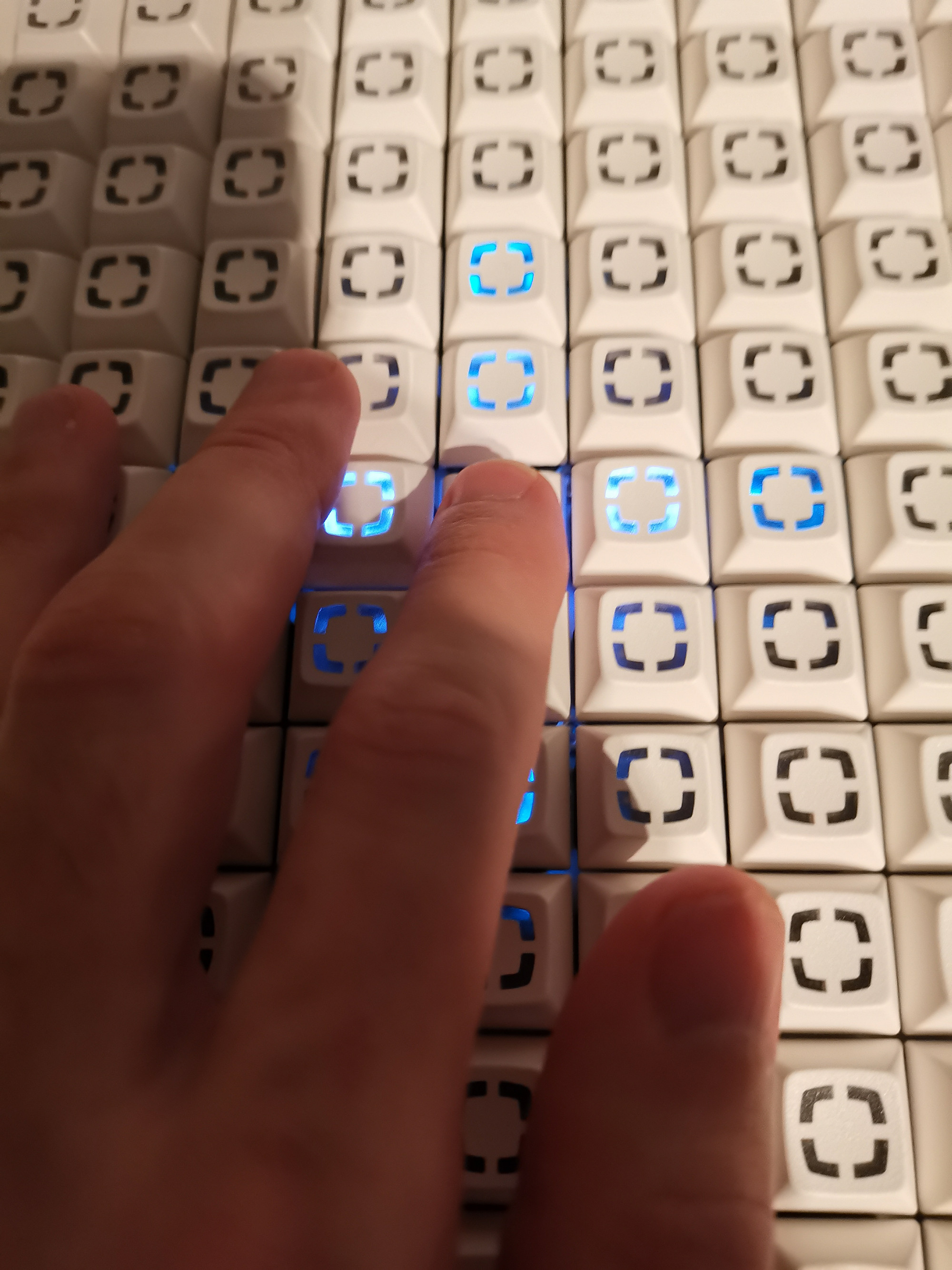
7.2 Test Matias key function
Flip the neo plate over and test each key function.
Press the keys and observe the light show!
If a single key fails to light up the LED row and column check that:
Both Matias pins are present and not broken off
Both pins are soldered
Diode is present and soldered with correct polarity
If the switch behavior is erratic, then the issue lies either with the cabling, or the input or sink side of the matrix.
Disconnect and test cables and rebuild if necessary
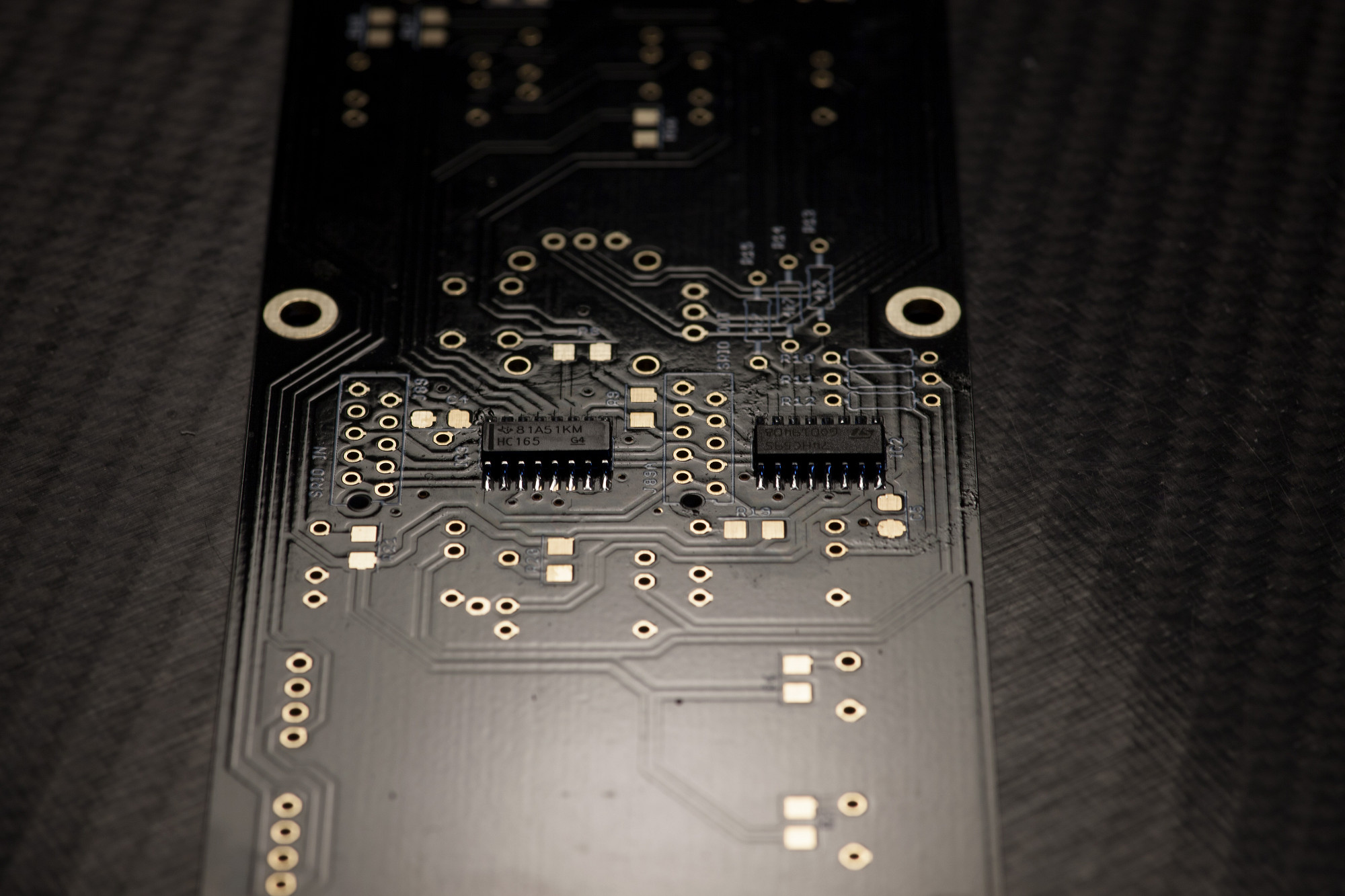
If a column of four switches doesn't work correctly, the issue is with the 74HC165 chips or 10k resistors
If a row of switches doesn't work correctly, the issue is with the 74HC595 chip
Flip the neo plate over and test each key function.
Press the keys and observe the light show!
If a single key fails to light up the LED row and column check that:
Both Matias pins are present and not broken off
Both pins are soldered
Diode is present and soldered with correct polarity
If the switch behavior is erratic, then the issue lies either with the cabling, or the input or sink side of the matrix.
Disconnect and test cables and rebuild if necessary
If a column of four switches doesn't work correctly, the issue is with the 74HC165 chips or 10k resistors
If a row of switches doesn't work correctly, the issue is with the 74HC595 chip
7.3 Install all PCBs in case
If it is not already present, flip the neo tray over. Leave the last MOW10 cable sitting outside the case when flipping as shown.
Position the axes board, connect the cable and fix the axes board in place. (Note that here I mounted the standoffs to the PCB first.)
If it is not already present, flip the neo tray over. Leave the last MOW10 cable sitting outside the case when flipping as shown.
Position the axes board, connect the cable and fix the axes board in place. (Note that here I mounted the standoffs to the PCB first.)
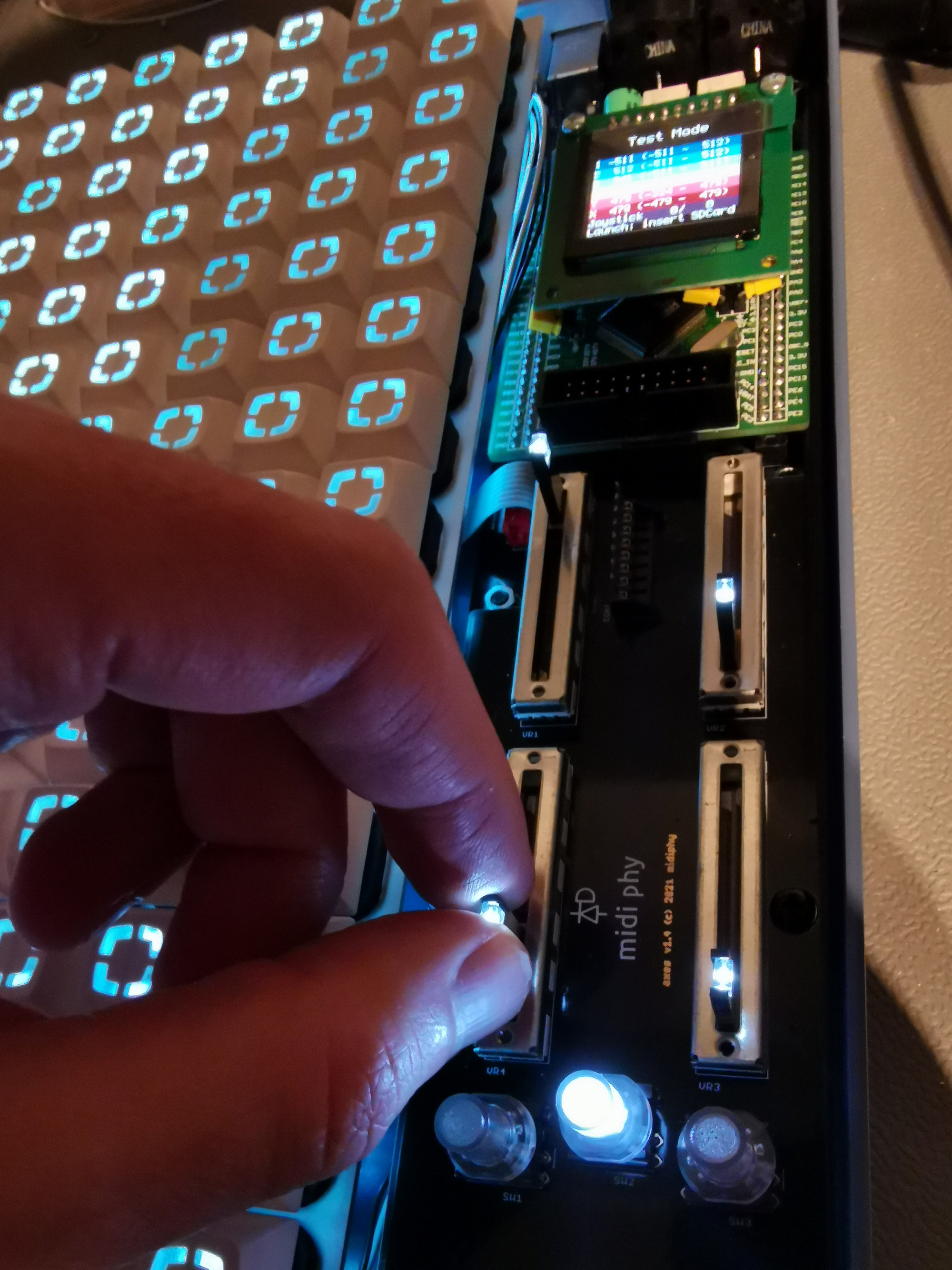
7.4 Test axes board
Power up in test mode (without inserted microSD card) and check the function of the sliders, switches and joystick.
In this test mode, you can evaluate the even illumination of the key area with different colors. If there are any "darker spots", the underlying ePixel LEDs may have been overheated during soldering - while they are still operational, they are usually noticably darker than the other LEDs. Replace any affected ePixels as described in step 7.1.
After that, insert the microSD card.
7.5 Attach bottom case screws
Loosely attach screws in the corners and check that the alignment is okay. As a sanity check, make sure all boards still function correctly.
Then proceed to screw in all screws on the base.
Loosely attach screws in the corners and check that the alignment is okay. As a sanity check, make sure all boards still function correctly.
Then proceed to screw in all screws on the base.
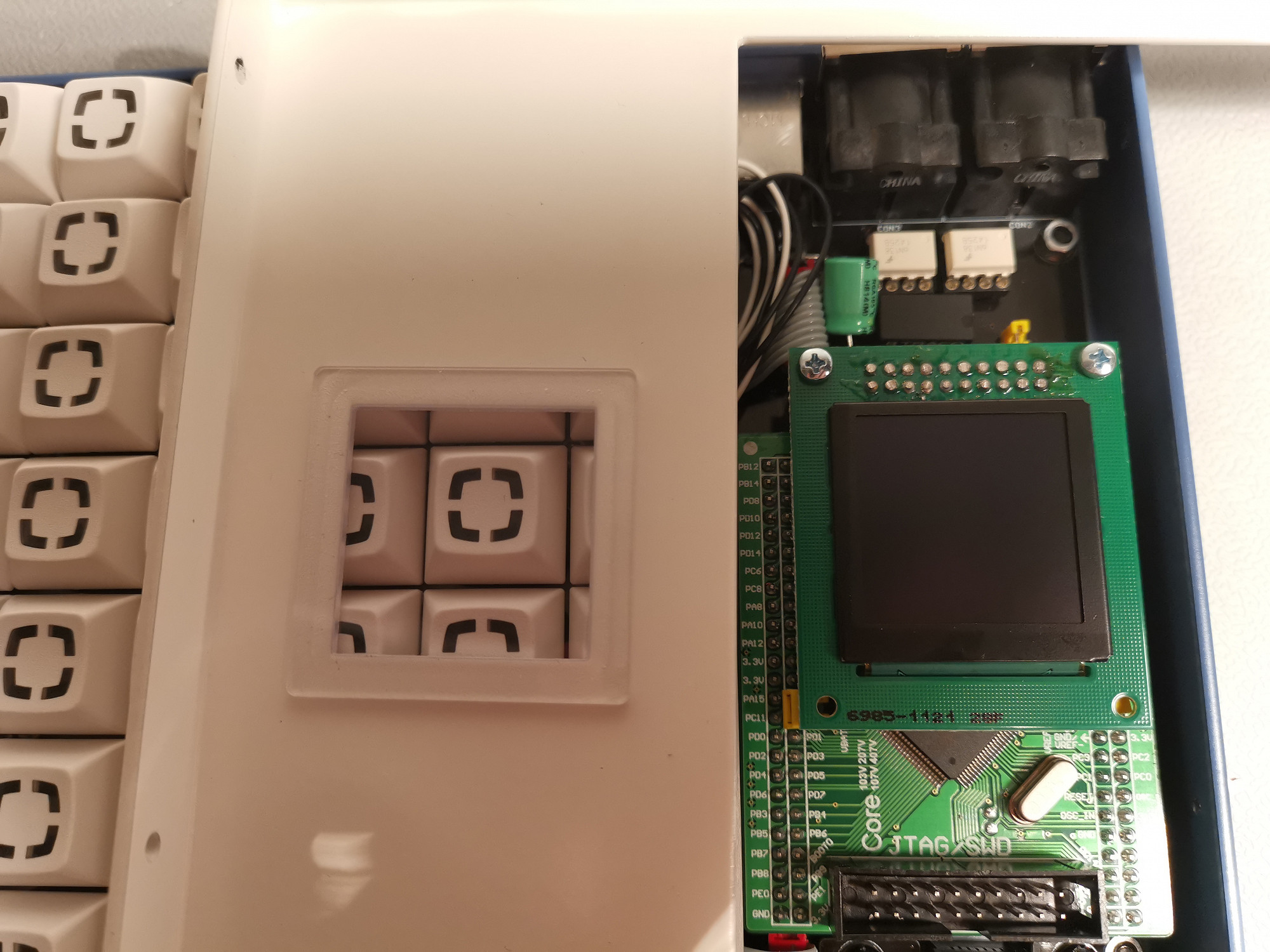
7.6 Press-fit screen protector in white case top
Normally this should fit in with no glue or tape required.
If not done already, remove the OLED protective film now.
Normally this should fit in with no glue or tape required.
If not done already, remove the OLED protective film now.
7.7 Screw in white case top
Place the white cover over the top and use the sheet metal screws to secure it.
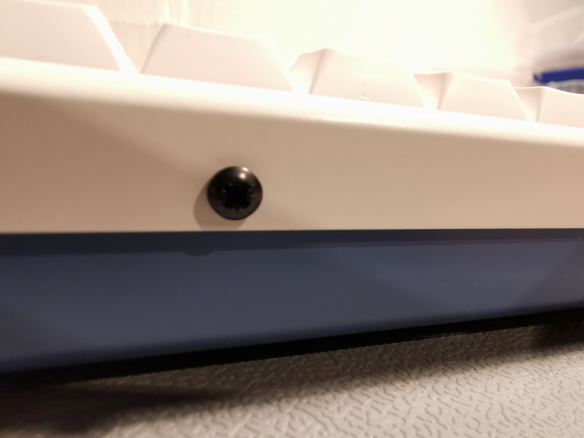
If the fit around certain keys is too tight, it is possible to loosen the rear panel screws slightly and find a better position.
Note: always turn metal screws backwards a bit until you feel a "click" before you turn them forwards to fasten them. This procedure will make sure, the screw thread is at the same position as the already cut metal case thread. Then carefully fasten the screw. This will avoid unwanted "metal scrapings" or cutting a second thread.
Place the white cover over the top and use the sheet metal screws to secure it.
If the fit around certain keys is too tight, it is possible to loosen the rear panel screws slightly and find a better position.
Note: always turn metal screws backwards a bit until you feel a "click" before you turn them forwards to fasten them. This procedure will make sure, the screw thread is at the same position as the already cut metal case thread. Then carefully fasten the screw. This will avoid unwanted "metal scrapings" or cutting a second thread.
7.8 Congratulations!
Well done on assembling your epic mechanical grid controller!
Well done on assembling your epic mechanical grid controller!